EasyManua.ls Logo

KEB COMBIVERT H6 User Manual

KEB COMBIVERT  H6
40 pages
To Next Page IconTo Next Page
To Previous Page IconTo Previous Page
Page #28 background imageLoading...
Page #28 background image
6.3.3 Setting of status bits by the SBC function
The current through the brake can measured at brake release.
co82 ext. modules ctrl word
Bit 0 safety module current sense
Value COMBIVIS text Function
0 SM-CS-off Brakecurrentmeasurementoff;atthestateofthe
safety module (sb29) only the bits 8 & 22 are set. Bit
0, 7 & 21 are unaffected by the current measurement.
1 SM-CS-on Brake current measurement on (default)
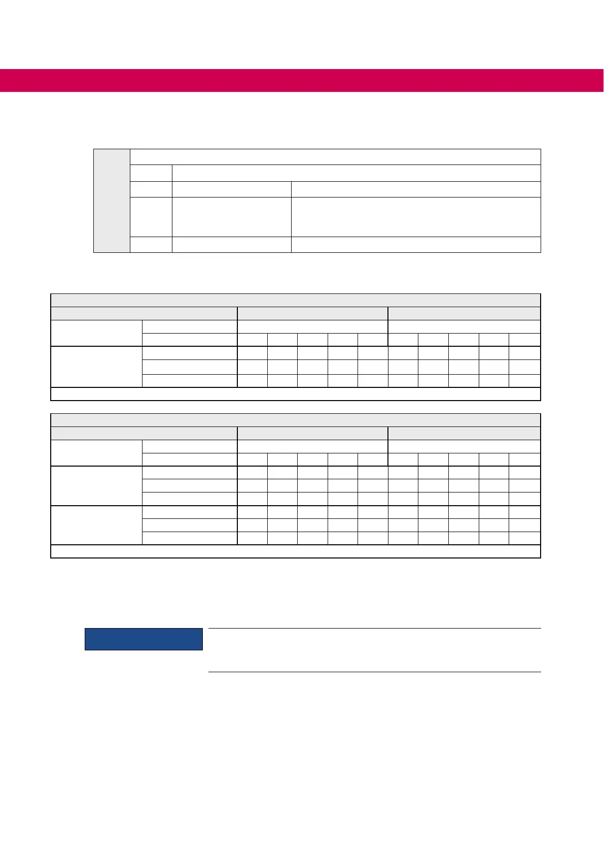
Depending on the hardware, the number of activated brakes, the setting of co82 and the current
measurement the following bits in sb29 are set:
Single axis module
Current measurement on (co82 = 1) off (co82 = 0)
activated Brake bit in sb29 bits in sb29
Current 0 7 8 0 7 8
A
co21 bit 4=1
<0.1 A 0 1 0 1
0.1 A…Imax 0 0 0 1
>Imax 1 1 0 0 1
Table 14: Setting of status bits by the SBC function
Double axis module
Current measurement on (co82 = 1) off (co82 = 0)
activated brake(s) bit in sb29 bits in sb29
Current 0 7 8 21 22 0 7 8 21 22
A
co21 bit 4=1
<0.1 A 0 1 0 1 0 1
0.1 A…Imax 0 0 0 1 0 1
>Imax 1 1 0 0 1 0 1
B
co21(B) bit 4=1
<0.1 A 0 1 0 1 0 1
0.1 A…Imax 0 0 0 1 0 1
>Imax 1 1 0 0 1 0 1
Table 15: Setting of status bits by the SBC function
„–“ in the table means, the respective bit is not affected by the function.
The control of the brake is reset to not released and the status LED is set to red when there is an error
caused by the current measurement.
Attention
Pay attention to response time
Since the current rise is slowly at high inductances of the brakes, the
error response time to a fault current is max. 100 ms.
28
FUNCTIONAL DESCRIPTIONS

Table of Contents

Question and Answer IconNeed help?

Do you have a question about the KEB COMBIVERT H6 and is the answer not in the manual?

KEB COMBIVERT H6 Specifications

General IconGeneral
BrandKEB
ModelCOMBIVERT H6
CategoryController
LanguageEnglish

Summary

1 Basic Safety Instructions

1.2 Electrical connection

Provides instructions and warnings for electrical connections.

1.3 Start-up and operation

Covers procedures and safety for initial startup and ongoing operation.

2 Product Description

2.1 Device identification

Details the numerical codes for identifying safety module types.

3 Safety Functions

3.2 Safe torque off (Safe Torque Off - STO)

Explains the STO safety function and its characteristics.

3.2.1 Emergency stop according EN 60204

Describes how STO achieves emergency stop categories 0 and 1 per EN 60204.

3.2.2 Classification of STO according IEC 61508

Classifies STO function according to IEC 61508 standards, including PFH and PFD values.

3.2.3 Classification of STO according EN ISO 13849

Classifies STO function according to EN ISO 13849 standards, including Category, MTTFd, and DC.

3.3 Safe brake control (Safe Brake Control – SBC)

Explains the SBC safety function for controlling external brakes.

3.3.2 Classification of SBC according IEC 61508

Classifies SBC function according to IEC 61508 standards, including PFH and PFD values.

3.3.3 Classification of SBC according EN ISO 13849

Classifies SBC function according to EN ISO 13849 standards, including Control category, MTTFd, and DC.

4 Description of the Terminals

5 Installation

6 Functional Descriptions

6.2 Function description STO

Details the safety-related disconnection mechanism of the STO function.

6.3 Functional description SBC

Explains the two-channel circuit operation of the SBC function for brake control.

7 Wiring Examples

8 Change of the Safety Module

Related product manuals