CP 503/A, CP 505/A,D,K, CP 507/
A,C
Displays and operating elements
Project engineering manual V1.06
23
© KEBA 2021
4 Displays and operating elements
4.1 Diagnosis display (DIAG)
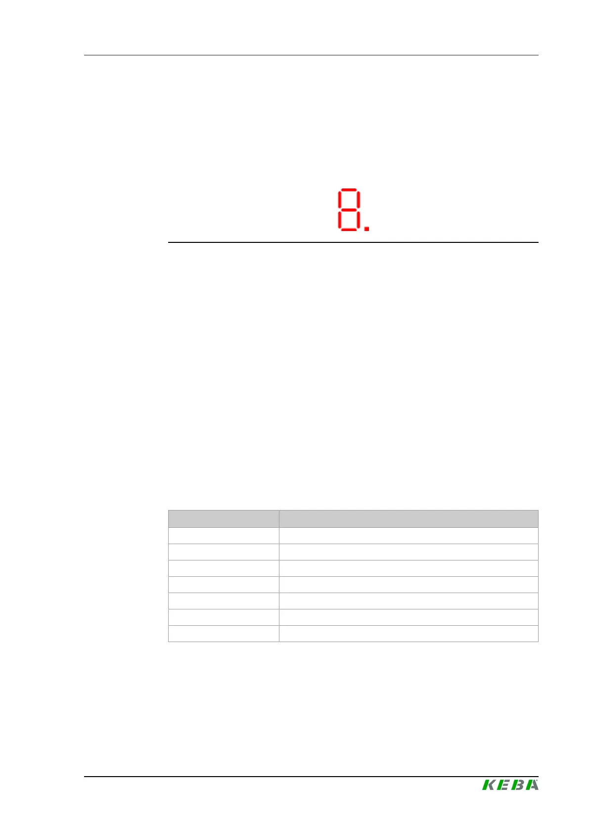
A single-digit 7-segment display on the front side of the CPU modules indi-
cates the start-up and operating modes.
Fig.4-8: 7-segment display
The following applies in general for the 7-segment display:
● Numbers > 0 during the start-up denote the progress
● Different characters (e.g. □, II, ...) or capital letters denote the operating
status after start-up
● The decimal point serves as load display. A flashing decimal point sig-
nals that the CPU load is in the allowed range. If the decimal point stops
blinking, then the CPU is overloaded and correct operation is no longer
guaranteed.
● Errors are displayed parallel to the states.
For further information see chapter "Diagnosis".
4.2 Status LED
A status LED is located on the front top right-hand side.
Status LED
Display Meaning
Dark No supply voltage
Orange Initialization phase
Flashing orange Command is executed
Green Control in normal operation
Flashing green Control stopped
Red Error status, control inactive
Flashing red Crashreport is written
 Loading...