CP 503/A, CP 505/A,D,K, CP 507/
A,C
Connections and wiring
Project engineering manual V1.06
43
© KEBA 2021
CAN
Pin-No. Signal designation Input/output
1 CAN+ CAN bus signal Input/output
2 CAN- CAN bus signal Input/output
3 SGND
CAN signal ground
(Ground)
---
4 n.c. Not connected ---
5 n.c. Not connected ---
6 SHLD Optional shield ---
7 n.c. Not connected ---
8 GND
Optional signal ground
(Ground)
---
Information
The connection SGND (Signal Ground) and GND (optional ground connec-
tion) are connected internally. The designation was chosen according to the
norm CiA® (CAN in Automation).
6.7.2 Bus termination
To activate the bus termination of the first or the last participant, the DIP
switch (S1) on the front of the module must be set (see "CAN configuration").
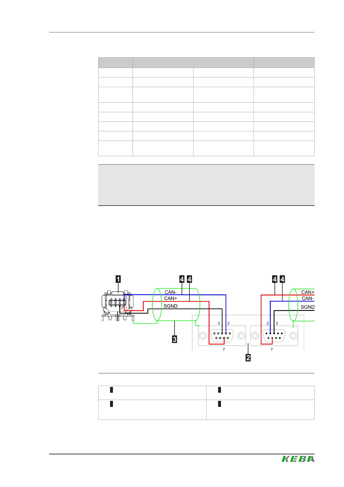
6.7.3 Connection example
Fig.6-30: Connection example für CAN circuit
1 ... Module (End participant with bus
termination)
2 ... CAN participant
3 ... Shield (double sided and extensive
attached to the provided connection
parts)
4 ... Twisted wire pairs
 Loading...