CP 503/A, CP 505/A,D,K, CP 507/
A,C
Connections and wiring
Project engineering manual V1.06
40
© KEBA 2021
Cross-section
Refer to the manufacturer-specific data sheet of the of the female connec-
tors used for type, cross-section and material. For additional information,
please see "Accessories".
The actual permissible wire cross-section is specified by the electrical condi-
tions of the connected equipment an the female connectors used:
● Max. load current and required heat dissipation through the connected
wire at maximum ambient temperature.
● Permissible voltage drop for error-free operation of the connected equip-
ment.
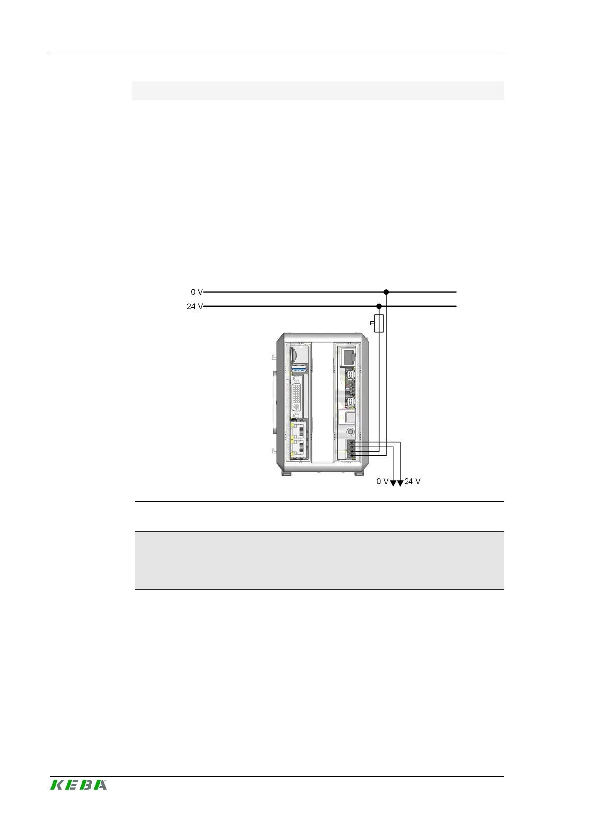
6.1.1 Connection example
Fig.6-26: Connection example
Information
To avoid problems with potential differences and compensation currents, it
is recommended to bundle all 0 V potentials in a star point.
6.2 EMC and wiring guidelines
Pay attention from the outset to careful wiring and shielding according to the
given guidelines.
Further information: See system manual.
 Loading...