ection 9: Speed scanning for increased test throughput DAQ6510 Data Acquisition / Multimeter System
9-2 DAQ6510-900-01Rev. A / April 2018
Device connections
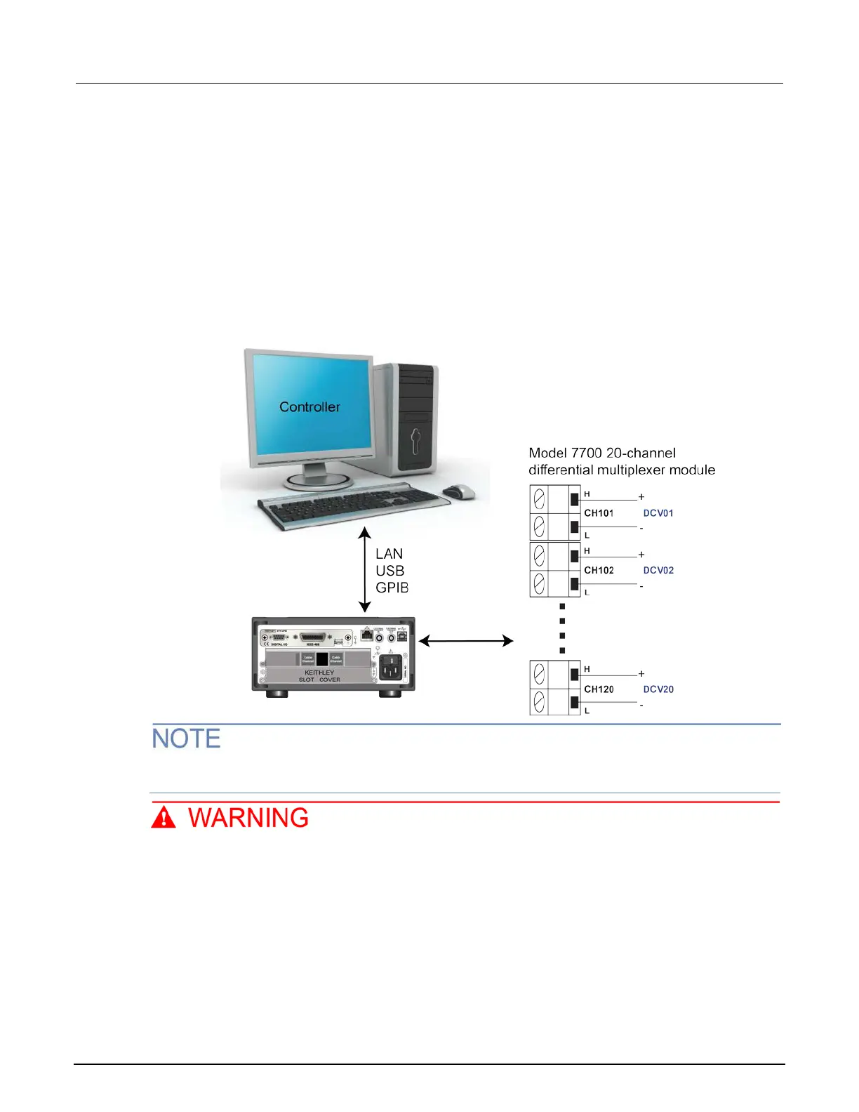
This example assumes a setup optimized for the greatest speed where the DAQ6510 uses either the
7700 or 7710 20-channel differential multiplexer module multiple to monitor the following signals; the
example code is the same for each.
The controlling computer can use either LAN, USB, or GPIB to reach scan and data transfer speeds
comparable to those of the original factory setup. The GPIB interface requires an optional
communications accessory.
See the following image for the connection example.
Figure 43: DAQ6510 speed scanning instrument and device connection
The 7700 replaces the 7710 for the second run of the program code for comparison and assumes
the same input signals to channels 101 to 120.
To prevent electric shock, test connections must be configured such that the user cannot
come in contact with test leads or any device under test (DUT) that is in contact with the
conductors. It is good practice to disconnect DUTs from the instrument before powering the
instrument. Safe installation requires proper shields, barriers, and grounding to prevent
contact with test leads.

 Loading...


