el DMM7510 7½ Digit Multimeter User's Manual Section 8:
Grading and binning resistors
DMM7510-900-01 Rev. B / May 2015 8-3
If a resistor passes the 20 % limit test, the resistance value is checked against Limit 2, which is the
10 % limit value. If the resistor fails this limit inspection, the resistance is outside of the 10 %
tolerance band. The trigger model outputs the Limit 2 Fail Pattern, which causes the component
handler to place the resistor in the Limit 2 fail bin (10 % fail bin).
If a resistor passes the 10 % limit test, the resistance value is checked against Limit 3, which is the
5 % limit value, and so on. If a resistor passes all the limit tests, the trigger model outputs the Overall
Pass Bit Pattern, which causes the component handler to place the resistor in the all pass bin.
For this example, the same fail pattern is assigned to both the lower and upper bounds of the limits.
Therefore, a fail bin contains resistances values in the range R-P% to R+P%. P in this example is 20,
10, 5, or 1. You can assign different bit patterns for different limit values.
Trigger model template: GradeBinning
The trigger model template contains the settings for the number of components, digital I/O, and limits.
The command parameters for the template are described in the following command and table.
SCPI command usage:
:TRIGger:LOAD "GradeBinning", <components>, <startInLine>, <startDelay>,
<endDelay>, <limit1High>, <limit1Low>, <limit1Pattern>, <allPattern>,
<limit2High>, <limit2Low>, <limit2Pattern>, <limit3High>, <limit3Low>,
<limit3Pattern>, <limit4High>, <limit4Low>, <limit4Pattern>, "<bufferName>"
TSP command usage:
trigger.model.load("GradeBinning", components, startInLine, startDelay, endDelay,
limit1High, limit1Low, limit1Pattern, allPattern, limit2High, limit2Low,
limit2Pattern, limit3High, limit3Low, limit3Pattern, limit4High, limit4Low,
limit4Pattern, bufferName)
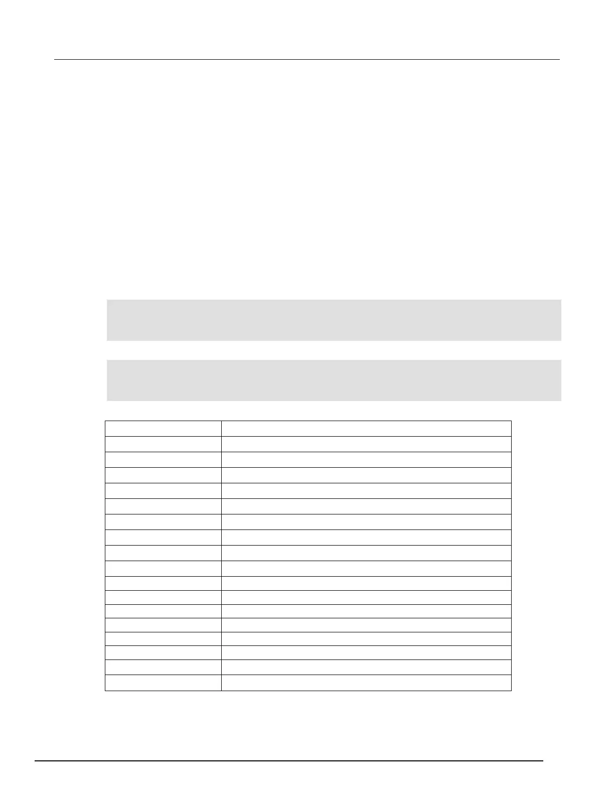
Parameter list
Digital I/O line 5
100 ms
R = 100 Ω, P = 20 %, 100+20 % = 120 Ω
R = 100 Ω, P = 20 %, 100-20 % = 80 Ω
Bin 1 Fail Pattern 15: drive all digital I/O lines high (1111)
All Pass Pattern 4: drive line 3 high (0100)
R = 100 Ω, P =10 %, 100+10 % = 110 Ω
R = 100 Ω, P =10 %, 100-10 % = 90 Ω
Bin 2 Fail Pattern 1: drive line 1 high (0001)
R = 100 Ω, P =5 %, 100+5 % = 105 Ω
Ω
Ω
Bin 3 Fail Pattern 2: drive line 2 high (0010)
R = 100 Ω, P =1 %, 100+1 % = 101 Ω
R = 100 Ω, P =1 %, 100-1 % = 99 Ω
Bin 4 Fail Pattern 3: drive line 1 and 2 high (0011)
In this example, the reading buffer is set to
北京海洋兴业科技股份有限公司(证券代码:839145)

 Loading...


