7½ Digit Multimeter User's Manual Section 10:
Capturing and analyzing waveforms
DMM7510-900-01 Rev. B / May 2015 10-11
Inductor current linearity with varying load
The inductor current is expected to be a linear triangular waveform with varying amplitude, depending
on the loading at the output terminals. The current increases linearly when energy is stored into the
inductor and decreases when energy discharges from the inductor. Any non-linearity in the slope of
the triangle waveform indicates inductor saturation, which is likely caused by overloading the output.
For this test, you:
• Connect the 3 Ω load resistor to the output terminals of the buck converter
• Connect test leads to the output terminals of the buck converter
• Supply 12 V to the input terminals of the buck converter
• Reset the instrument
• Select the digitize current function and set sample rate to 500 ksample per second
• Set sample count to 50
• Display the graph
• Repeat these steps with 4 Ω and 8 Ω resistive loads to see the change in the inductor current
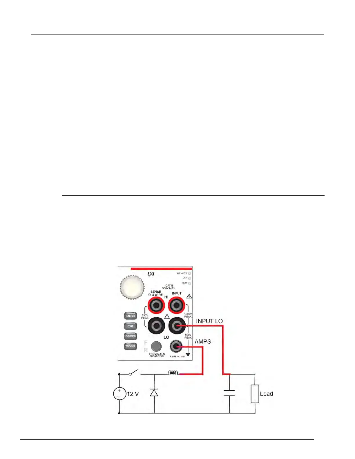
Inductor current measurement device connections
Connect the test leads as shown in the following figure.
You can use either the front or rear inputs. Ensure that the front-panel TERMINALS button is set
correctly (F displayed for front; R displayed for rear). Note that you must use either the front terminals
or rear terminals — you cannot mix connections.
Both front-panel and rear-panel connections are safety banana jacks. You can make these
connections with two insulated banana cables (for example, the leads included with the Keithley
Instruments Model 1756 Standard Test Lead Kit).
Figure 40: Inductor current linearity test connections
北京海洋兴业科技股份有限公司(证券代码:839145)

 Loading...


