1. Preparation for adjustment
Test disc
MD SECTION
Type Test disc
1 High reflection disc TGYS1 (SONY)
2 Low reflection disc Recording minidisc
3 Head Adjusting transparent
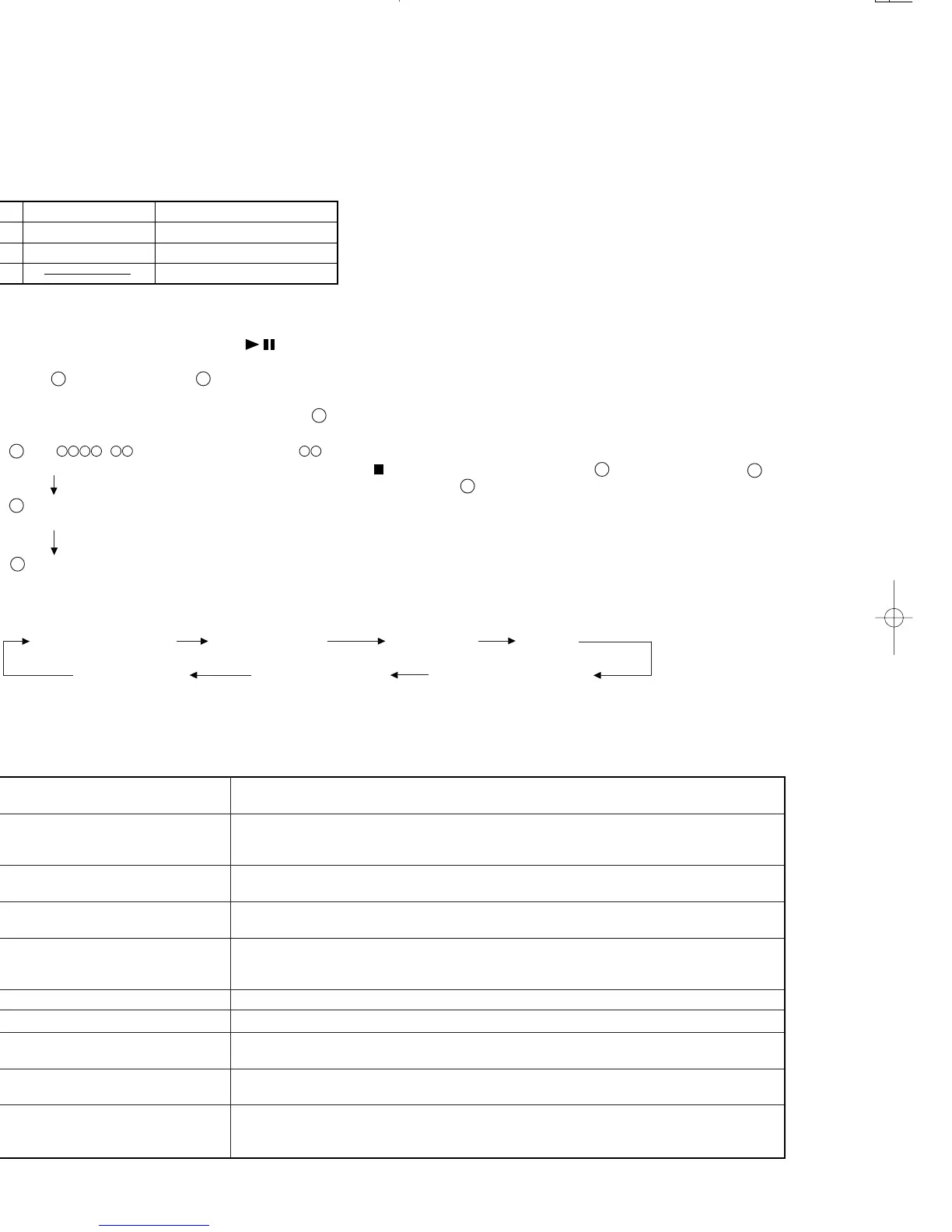
2. Test mode
Test mode setting method
1. Holding
After 3sec, take your hand off the RESET button first.
down the ENTER button and
(PLAY/PAUSE) button, press the RESET button.
(State A is changed to state B .)
2. Insert the playback disc 1 (high reflection disc) or recording disc 2 (low reflection disc).
(State C is set.)
(During disc loading : display LOADING)
Thus, the test mode state is set.
A tsm
e : TEST MODE represents version of MD microcomputer.
TEST STOP state (When the (STOP) button is ressed in the C state, the indication A
is restored. To restore C again, press the ENTER button.)
B EJECT
TEST
C AUTO
TEST
Entering the specific mode
Whenever the button ENTER is pressed, the mode is changed.
AUTO pre-adjustment AUTO adjustment RESULT SUB RESULT
EEPROM setting MANUAL adjustment MANUAL pre-adjustment
• Canceling the test mode
When the POWER button is pressed, the test mode is canceled, and the POWER OFF state is set.
• Test Mode
1. AUTO pre-adjustment mode • Automatic pre-adjustment is performed. (After adjustment the grating adjustment mode is set.)
• The adjustment value is output with the aid of system controller interface.
2. AUTO adjustment mode • Automatic adjustment is performed.
• The adjustment value is output with the aid of system controller interface.
• Continuous playback is performed. (Error rate indication, jump test)
3. RESULT sub-mode • The measurement value, set value and calculated value are indicated.
• The set value is changed manually (in servo OFF state).
4. RESULT mode (final adjustment) • The set value (after calculation) is indicated.
• The set value is changed manually (in servo OFF state).
5. MANUAL pre-adjustment mode • RF side manual adjustment is performed.
• Focus and tracking signal ATT manual adjustment is performed.
• Focus and tracking signal offset setting is performed.
6. MANUAL adjustment mode • Focus and tracking signal ATT manual adjustment is performed.
7. EEPROM setting mode • This mode does not use on the occasion of service.
8. TEST-PLAY mode • Continuous playback from the specified address is performed.
• C1 error rate measurement, ADIP error rate measurement.
9. TEST-REC mode • Continuous recording from the specified address is performed.
• Change of record laser output (servo gain is also changed according to laser output)
10. EJECT mode • TEMP setting (of EEPROM setting)
• CONTROL setting (of EEPROM setting)
• Setting of laser power (record/playback power)

 Loading...