 Loading...
Do you have a question about the Kenwood PS Series and is the answer not in the manual?
| Category | Power Supply |
|---|---|
| Manufacturer | Kenwood |
| Input Frequency | 50/60 Hz |
| Dimensions | Varies by model |
| Weight | Varies by model |
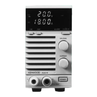
| Output Voltage | Adjustable |
| Line Regulation | ≤0.01% + 3mV |
| Load Regulation | ≤ 0.01% + 3 mV |
| Ripple and Noise | ≤1mVrms |
| Display | Digital LED |
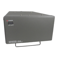
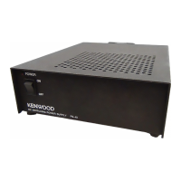
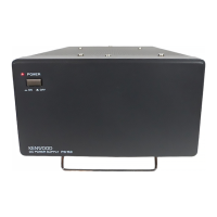
| Model | PS Series |
| Protection | overvoltage, overtemperature |
| Input Voltage | 100/110/120/220/230/240 VAC (depending on the model and region) |