16
Preparations
Setting up the system
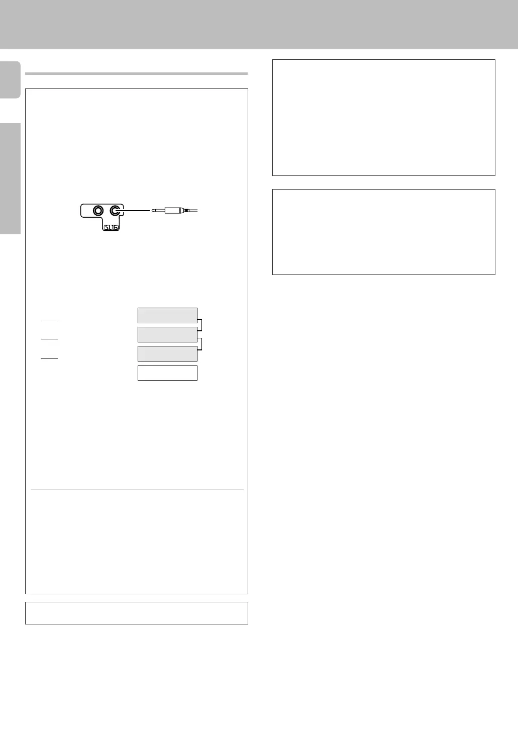
Connecting the system control
Connecting system control cords after connecting a KENWOOD
audio component system lets you take advantage of convenient
system control operations.
This unit is compatible only with the [SL-16] mode. The system
control operation is not available if the unit is connected in the
[XS8], [XS], or [XR] connection mode.
If your component has the mode select switch, set the connected
components to the [SL16] mode.
[
SL16]
[
SL16] [XS] [XS8] [XR]
[
SL16] [XS] [XS8]
[XS]
SYSTEM
CONTROL
cord
Receiver
Cassette deck
or MD recorder
CD player
Record player
• In order to take advantage of the system control operations, the
components must be connected to the correct jacks. To use a CD
player it must be connected to the CD jacks. To use a cassette deck
(or MD recorder) it must be connected to the MD/TAPE jacks. When
using more than one CD player (etc.) only the one connected to the
specified jacks may be connected for system control.
• Some CD players and cassette decks are not compatible with the
[SL16] system control mode. Do not make system connections with
equipment that is not [SL16] compatible.
• Some MD players are not system control compatible. You cannot
make system control connections to this kind of equipment.
Notes
1. [SL16] equipment cannot be combined with [XR], [XS], and [XS8]
equipment for system operations. If your equipment consists of this
kind of combination, please do not connect any system control cords.
Even without system control cords, normal operations can be carried
out without effecting performance.
2. Do not connect system control cords to any components other than
those specified by KENWOOD. It may cause a malfunction and
damage your equipment.
3. Be sure the system control plugs are inserted all the way in to the
system control terminals.
• You may connect the system control cord to either the left or right jack.
EXAMPLE: [SL16] mode connections
The underlined portion represents the setting of the system control
mode.
SYSTEM CONTROL
cord
Do not connect a system control cord to a cassette deck
connected to the MONITOR jacks.
SYSTEM CONTROL OPERATIONS
Remote Control
Lets you operate this unit with the system remote supplied with the
receiver.
Automatic Operation
When you start playback from a source component, the input selector
on this unit switches to that component automatically.
Synchronized Recording
Lets you synchronize recording with the start of playback when record-
ing from CD, MD or analog discs.
Registering setup codes for KENWOOD audio components
• If you own remote controllable KENWOOD audio components that are
not compatible with system control, registering the setup code en-
ables you to control those components using the remote control
supplied with this unit (without connecting system control cords). To
register setup codes for your remote controllable KENWOOD audio
components, see “Registering setup codes for other components”.
‹
SYSTEM
CONTROL
*509/07-18/EN 3/15/01, 2:01 PM16
 Loading...