6319 690 01 Rev. -- KohlerEngines.com
Electrical System
BATTERY CHARGING SYSTEM
NOTE: Observe following guidelines to avoid damage to electrical system and components:
● Make sure battery polarity is correct. A negative (-) ground system is used.
● Disconnect rectifi er-regulator plug and/or wiring harness plug before doing any electric welding on equipment
powered by engine. Also, disconnect all other electrical accessories in common ground with engine.
● Prevent stator (AC) leads from touching or shorting while engine is running. This could damage stator.
These engines are equipped with a 20 or 25 amp regulated charging system.
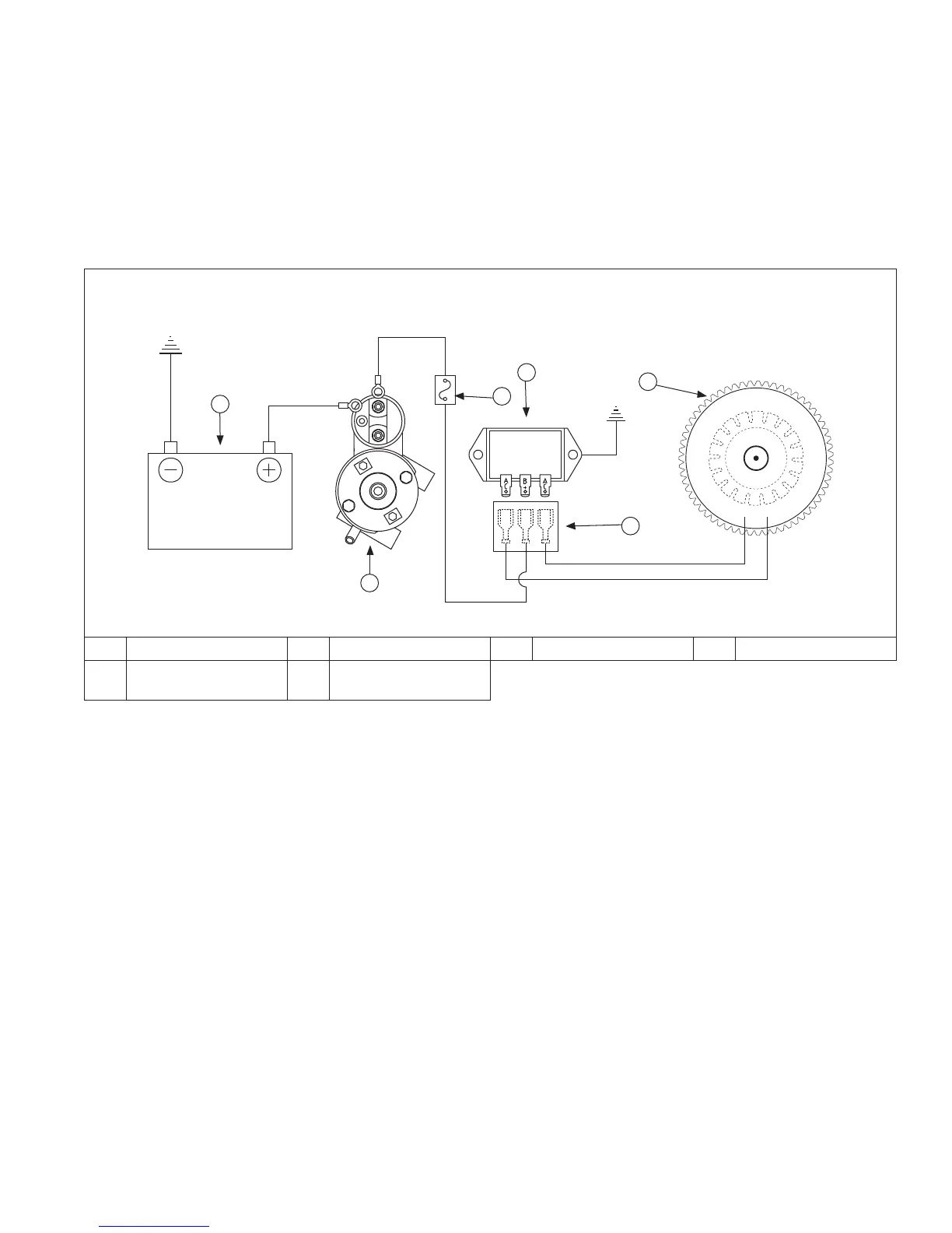
20/25 Amp Regulated Charging System
B
C
E
F
A
D
A Battery B Starter C Fuse D Rectifi er-Regulator
E Connector Block F
Flywheel Stator
Assembly
Stator
Stator is mounted on crankcase behind fl ywheel. Follow procedures in Disassembly and Reassembly if stator
replacement is necessary.
Rectifi er-Regulator
NOTE: When installing rectifi er-regulator, take note of terminal markings and install plug(s) accordingly.
NOTE: Disconnect all electrical connections attached to rectifi er-regulator. Testing may be performed with rectifi er-
regulator mounted or loose. Repeat applicable test procedure 2 or 3 times to determine condition of part.
Rectifi er-regulator is mounted on blower housing. To replace, disconnect plug(s), remove mounting screws, and
ground wire or metal grounding strap.
Testing rectifi er-regulator may be performed as follows, using appropriate rectifi er-regulator tester.
To test 20/25 amp rectifi er-regulators:
1. Connect tester ground lead (with spring clamp) to body of rectifi er-regulator.
2. Connect red lead from tester to middle terminal labeled B+.
3. Connect black leads from tester to both outer AC terminals on rectifi er-regulator.
4. Plug tester into proper AC outlet/power for tester being used. Turn on power switch. POWER light should be
illuminated and one of four status lights may be lit as well. This does not represent condition of part.
5. Press TEST button until a click is heard and then release. Momentarily one of four status lights will illuminate
indicating partial condition of part.
 Loading...