144 Section 8 Component Testing and Adjustment TP-6356 4/12
8.18 Remote Serial Annunciator
(RSA 1000)
Adapted from Instruction TT-1377 4/08.
The following information summarizes the setup items
when troubleshooting the remote serial annunciator
(RSA). Refer to the RSA installation instructions for
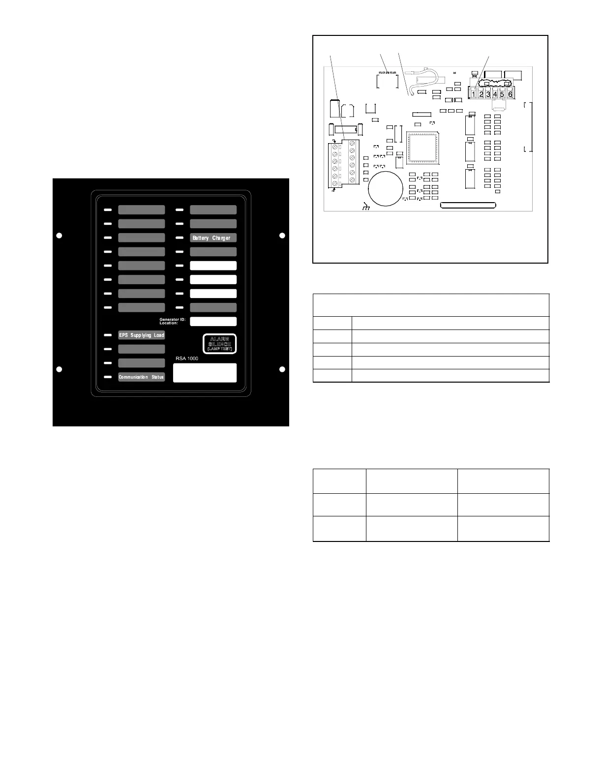
operation and function. See Figure 8-36 for RSA front
panel illustration. See Section 8.19, Communication
Module and Gauge Driver Circuit Board.
Overcrank
High Engine Temp.
Low Oil Pressure
Overspeed
Emergency Stop
Low Coolant Level
Low Coolant Temp.
Low Fuel
System Ready
Generator Running
Not-In-Auto
Common Fault
Battery Voltage
Alarm Silenced
On=High, Blink=Low
User Input #1
User Input #2
User Input #3
Figure 8-36 Remote Serial Annunciator (RSA)
8.18.1 DIP Switches
The RSA will function as master or slave by changing the
DIP switch position on the RSA board. See Figure 8-37
for RSA circuit board features.
The RSA annunciates faults using LEDs and an alarm
horn. Press the Alarm Silence/Lamp Test switch to test
the RSA indicator LEDs and horn. If the horn is activated
by a fault condition, press the Alarm Silence/Lamp Test
switch to quiet the alarm during servicing. The horn will
reactivate upon additional tests.
Set the SW1 DIP switches on the RSA master and
subsequent RSA slave (if used). See Figure 8-38. RSA
connected to controller MUST be assigned as the RSA
master.
GM31211-
1. TB12 user input/outputs and DC power supply connections
2. SW1 DIP switches
3. T3 isolation jumper
4. P27 RS-485 communication connections
R30
Z2
C16
543 21
SW1
R33
U7
R10
R22
C14
+
C1
R4
Z1
C12
R26
R34
R19
40
29
18
JP3
R3
R18
R1
C3
R38
Y1
R23
D1
TZ1
R31
D5
JP1
7
1
U3
39
28
17
U1
R8
Z3
R27
R35
R2
Q1
D6
C4
R9
U2
TB12
R20
R39
T2
R24
RN1
C11
C6
R7
R32
+
HN1
R28
R36
U8
VR1
R41
6
P27
P30
D2
R6
C13
U9
R25
D3
C10
U6
R12
Q2
C15
C2
R21
C8
R5
R37
C9
R29
D4
JP2
R40
1
2
3
4
5
6
7
8
9
10
11
12
GND
GND
+--
GND
+--
GND
VCC
RXD
XMIT
TXD
RS485
BARCODE
K1
U5
P28
TZ2
R13
C7
+
R17R14
L6
U4
T1
L5
C5
+
R15
TZ3
L7
L1
L3
L4
L2
R16
R11
T3
DISPLAY
RS--485 ISOLAT RS--485 NON--ISOLATED
T5
T4
+BAT
--
123 4
Figure 8-37 RSA Circuit Board
SW1 DIP Switches
(on = closed and off = open
SW1-1 Local ATS (on is local)
SW1-2 User input 1 (on is local)
SW1-3 User input 2 (on is local)
SW1-4 Master/Slave (on is master)
SW1-5 Not used
Figure 8-38 RSA DIP Switch Selections
See Figure 8-39 for a summary of the Emergency
Power System (EPS) Supplying Load (ATS)
annunciation sources depending upon DIP switch
position.
RSA SW1
Position
Decsion-Maker 3+
Controller
Decision-Maker 550
Controller
Local
(hard wired)
RSA connection to the
ATS
RSA connection to the
ATS
Remote
(RS-485)
Comm. module board
connection to the ATS
550 controller
connection to the ATS
Figure 8-39 EPS Supplying Load (ATS) Annunciation
Sources
When SW1-1 is OFF, the generator set controller
activates the EPS Supplying Load LED. When SW1-1 is
ON (local), transfer switch activates LED.
Note: When SW1-4 is in the slave position, DIP
switches SW1-1, SW1-2, and SW1-3 are not
functional as the RSA master annunciates the
RSA slaves.

 Loading...
