195Section 10 Governor AdjustmentsTP-6356 4/12
The digital isochronous governor kits replace
discontinued generator set governors. See
Figure 10-11. Replacement governors are shipped
unprogrammed. After installation and wiring, the
governor kit requires downloading the PST and
changing the default settings.
Service Kit
Governor
Assembly
Replaces:
GM36253 GM17644-4 A-249922
GM36254 GM17644-4 A-246045
GM38323 GM17644-4 324515, 324704, 326814,
336236, 336396
GM39342* GM17644-5 227264, 255932, 324547,
336397, 347840, 347841
GM39343 GM17644-6 GM22742
* Load share governor
Figure 10-11 Service Kits and Discontinued
Governors
The PST overwrites any original programs in the
governor controller’s nonvolatile memory. Make a
backup copy of the files onto a disk and store the disk in a
safe place.
The CD-ROM file contents can also be requested
through KOHLERnet. Use your SecurID to access the
KOHLERnet, click on the TechTools button, and follow
the instructions to request files.
Read the entire procedure before beginning. Install the
software onto a PC. Carefully follow these instructions
and any additional instructions that appear on screen
during the download procedure. The instructions
provided assume you know how to operate a PC.
Loading incorrect or incomplete files may cause
permanent damage to the governor controller’s logic
circuit board. Verify that the CD-ROM file contains
settings for your specific generator set and engine. Do
not attempt to modify the data files.
10.5.2 Kit Components
D COMM port cable (9-pin RS-232 DB9F serial port
connector to a RJ11M plug)
D CD-ROM including:
D Parameter Setup Tool Software
D Parameter Text Files
D Governor Parameter Detail Form
D Governor Parameter Summary Form
D TT-1399 Governor Programming Instructions
10.5.3 Features and Specifications
The microprocessor-based, digital isochronous
governor allows adjustment of set speed and gain.
Other adjustments include acceleration, deceleration,
ramp rates, idle speed set, and hold time. The COMM
port provides simple programming when connected to
the user’s PC. See Figure 10-12 for specifications and
Figure 10-13 for governor controller illustrations.
Specifications Value
Maximum Controlled Output Current 7Amps
Maximum Current Surge 14 Amps for 10 seconds
Input Signal from Magnetic Pickup 2.0 VAC RMS min. during
cranking
Ambient Operating Temperature
-- 4 0 _Cto+85_C
(--40_F to +185_F)
Environmental Protection Oil, water, dust resistant
via conformal coating and
die cast enclosure
Electrical Connections Euro-style terminal strip
Figure 10-12 Specifications
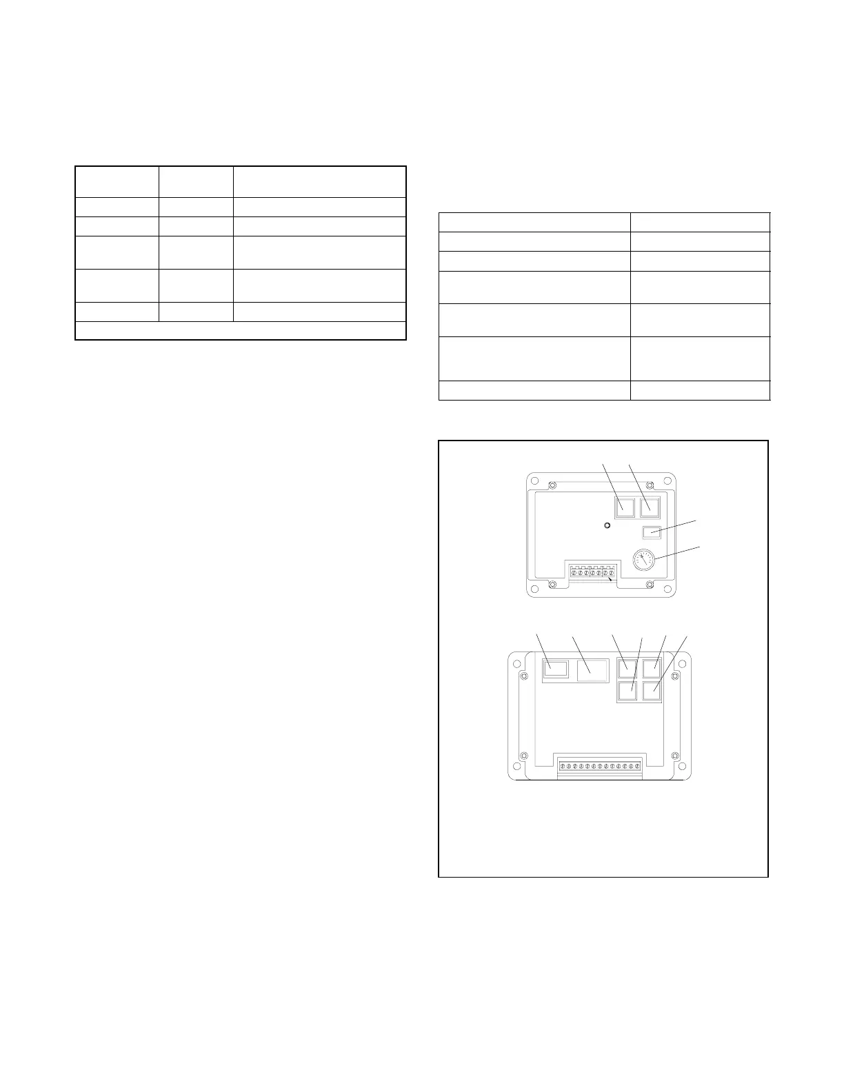
GM17644-B
SPEED
DEC INC
GAIN
BAT+
BAT--
ACT
ACT
MPU--SHIELD
MPU--
MPU+
COMM
(5)MPU+
(6)MPU--
(7)SHIELD
(3)ACT
(4)ACT
(2)BAT--
(1)BAT+
ENTERDEC
INC SELECT
(10)ILS REF (2.5V)
(9)ILS SIGNAL
(13)VDC
(12)INC SPEED
(11)DEC SPEED
(8)SPEED SEL
COM
1. Speed decrease
2. Speed increase
3. RJ11 c onnector
4. Gain potentiometer
5. RJ11 c onnector
Non-Load Share Model
Load Share Model
1
2
3
4
5678910
6. LED display
7. Increase
8. Decrease
9. Select
10. Enter
Figure 10-13 Governor Controller Functions

 Loading...
