TP-6356 4/12 27Section 2 Decision-Makerr 1 Troubleshooting
Section 2 Decision -Makerr 1 Troubleshooting
This section contains Decision-Makerr 1 relay
controller troubleshooting, diagnostic, and repair
information. See the respective generator set operation
manual for controller operation.
2.1 General Information
The following text covers the relay controller sequence
of operation during generator start, run, stop, and fault
shutdown modes. Use this information as a starting
point for controller fault identification. See Figure 2-1 to
identify internal components of the relay controller. Use
the LEDs on the controller circuit board to assist in the
troubleshooting process. An illuminated LED indicates
the respective relay is receiving power; the LED does
not indicate whether that relay is energized. See
Figure 2-2 and Figure 2-3.
A change in the circuit board affects the function of some
relays. Circuit board F-254717 has five relays with an
external K10 relay for engine run components. The
controller circuit board relays provide the following
functions:
D K1 fault shutdown relay
D K2 engine run relay
D K3 crank disconnect/flashing control relay
D K4 crank disconnect relay
D K5 fault lamp latch relay
D K10 auxiliary run relay (external)
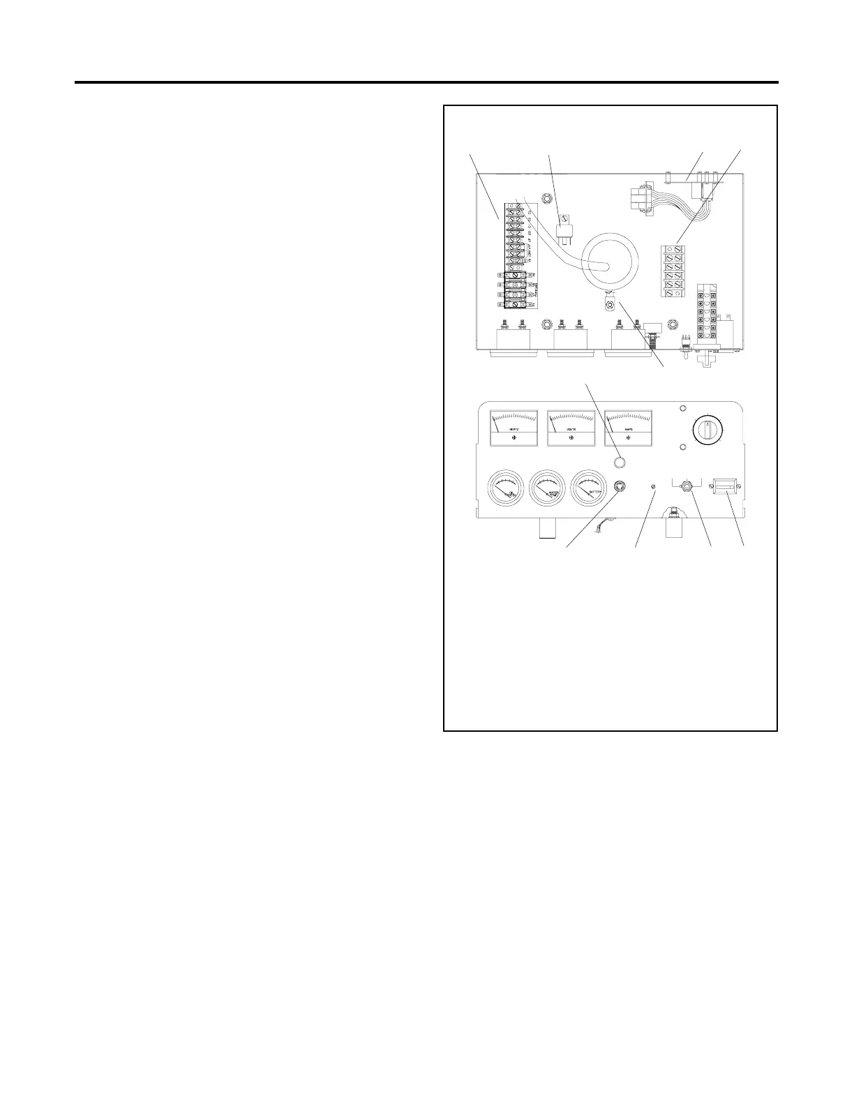
A-336598A-K
12 34
78910
6
5
1. TB2 terminal block
2. K10 relay
3. Controller main circuit board
4. TB1 AC terminal block
5. Ground strap
6. Fault lamp (front panel)
7. Hourmeter (front panel)
8. Generator set master switch (front panel)
9. Voltage adjust potentiometer (front panel)
10. 10-amp fuse (front panel)
Figure 2-1 Controller Internal Components

 Loading...
