45Section 3 Decision-Makerr 3+ TroubleshootingTP-6356 4/12
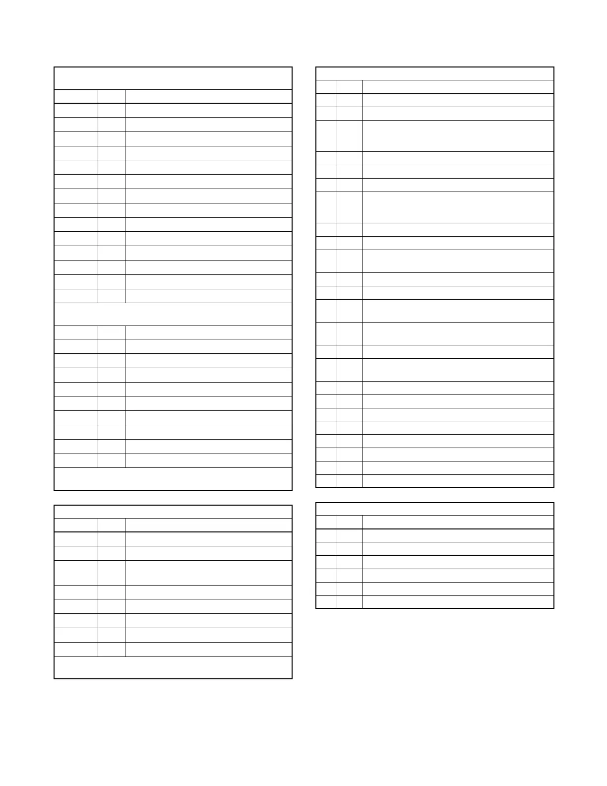
3.2 Circuit Board GM28725/GM64497 Terminal/Connector Identification
Controller Main Circuit Board
Terminal Strip TB1 (TB1A)
Terminal Wire Description
1 1A
Emergency stop relay (K1) coil negative
2 1
Emergency stop relay (K1) ground
3 42A
Battery voltage (fuse #1 protected)
4 2
Ground
5 70C
Generator set in cooldown mode signal
6 70R
Generator set in running mode signal
7 56
Engine air damper indicator (if equipped)
8 48
Emergency stop indicator
9 32A
Commonfaultline2
10 26
Auxiliary indicator
11 12
Overcrank indicator
12 39
Overspeed indicator
13 38
Low oil pressure indicator
14 36
High engine temperature indicator
Controller Main Circuit Board
Terminal Strip TB3 (TB1B)
Terminal Wire Description
15 60
System ready indicator
16 80
Not in auto indicator
17 41
Prealarm low oil pressure indicator
18 62
Low battery volts (active low*)
19 32
Common fault/prealarm line 1
20 35A
Low water temperature
21 40
Prealarm high coolant temperature indicator
22 63
Low fuel (active low*)
23 61
Battery charger fault (active low*)
* Check active low circuits for function by grounding designated
terminals.
Controller Main Circuit Board Terminal Strip TB2
Terminal Wire Description
1 1P
Prime power operation (requires optional kit)
2 2P
Prime power operation (requires optional kit)
3 3P
Prime power operation (ground) (requires
optional kit)
4 4P
Prime power operation (requires optional kit)
5 9
Crank mode (open-cyclic ground-continuous)
6 9A
Crank mode (ground)
7 4
Remote start (active low*)
8 3
Remote start (ground)
* Check active low circuits for function by grounding designated
terminals.
Controller Main Circuit Board P1 Connector Pins
Pin Wire Description
1 71 Output to K2 relay (crank relay) (fuse #3 protected)
2 2 Ground for speed sensor
3 70
Output to safeguard breaker terminal and K5 relay
(if equipped with electronic governor)
(fuse #3 protected)
4 — Alternator flash
5 10N Starter motor ground (--)
6 S2 Speed sensor shield ground
7 70
Output to fuel solenoid (FS) on diesel models or
ignition system (I.S.) on gas/gasoline models
(fuse #3 protected)
8 24 Battery positive to speed sensor (fuse #2 protected)
9 16 Input from speed sensor
10 31A
Input from low coolant level (LCL), positive
temperature coefficient (PTC) sensor
11 — Not used
12 14P Input from battery positive
13 31
Input from auxiliary delay shutdown, high oil
temperature (HOT), if used
14 31
Input from auxiliary delay shutdown, low coolant
level (LCL), if used
15 31 Input from auxiliary delay shutdown, if used
16 40
Input from pre-high coolant temperature (preHCT)
switch
17 30 Input from auxiliary immediate shutdown, if used
18 56 Input from engine air damper switch, if equipped
19 57 Input from K6 air damper relay (ground), if equipped
20 — Not used
21 34 Input from high coolant temperature (HCT) switch
22 13 Input from low oil pressure (LOP) switch
23 41 Input from pre low oil pressure (preLOP) switch
24 35A Input from low coolant temperature (LCT) switch
Controller Main Circuit Board P2 Connector Pins
Pin Wire Description
1 70 Output to engine gauges (fuse #3 protected)
2 30A Overvoltage auxiliary
3 V7F Input from AC crank disconnect & instrumentation
4 — Not used
5 V0 Input from AC crank disconnect & instrumentation
6 2 Engine ground

 Loading...
