
Do you have a question about the Kohler Decision-Maker 550 and is the answer not in the manual?
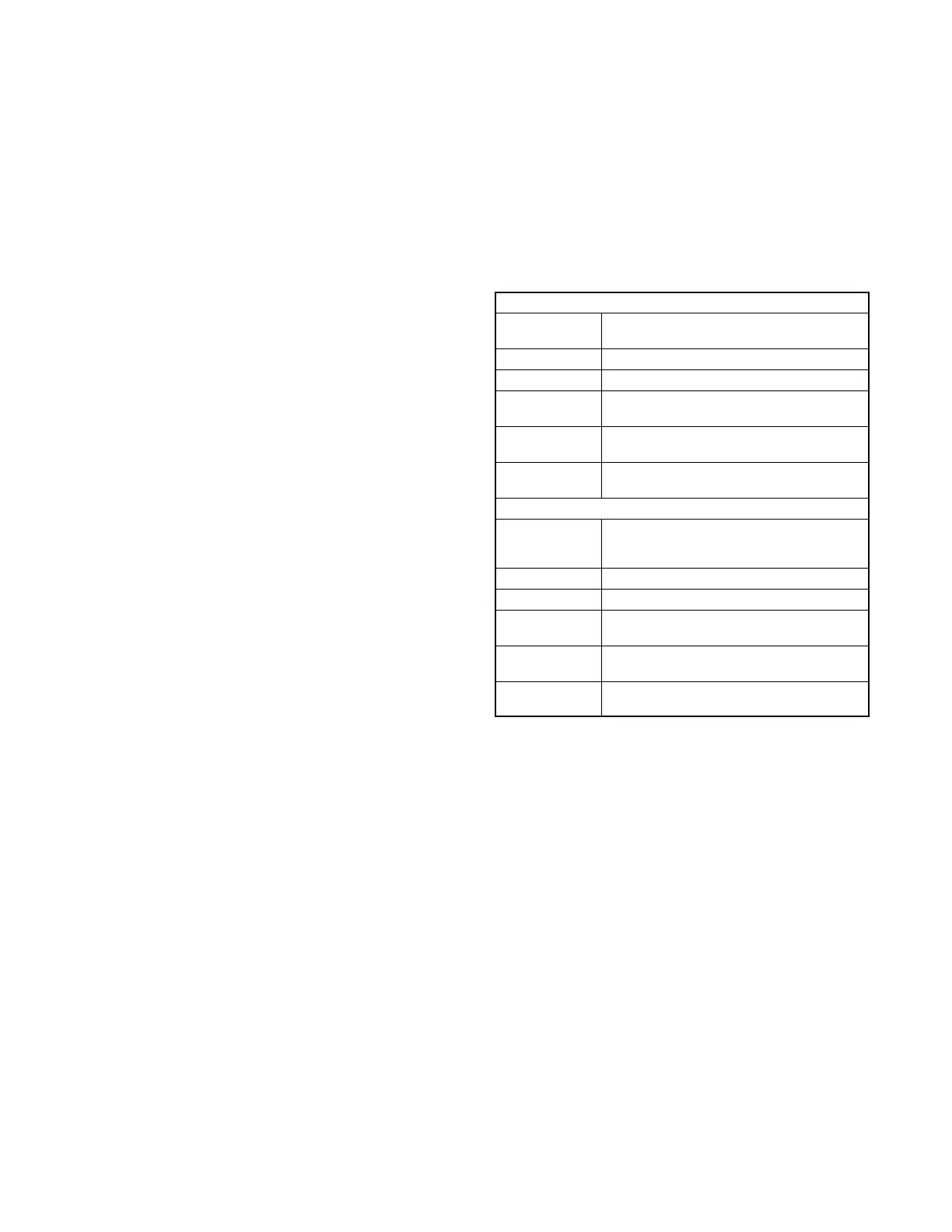
| Brand | Kohler |
|---|---|
| Model | Decision-Maker 550 |
| Category | Portable Generator |
| Language | English |
Instructions for recording product identification numbers from the generator set nameplate.
Instructions for recording controller description from available documentation or invoice.
Instructions for recording product identification information from the engine nameplate.
Safety precautions to prevent accidental starting of the generator set.
Safety precautions related to handling and servicing batteries, including acid and explosion hazards.
Safety precautions regarding fire hazards associated with fuel and engine operation.
Safety precautions regarding carbon monoxide hazards from exhaust systems.
Safety precautions for handling fuels, including explosive vapors and hazardous noise.
Safety precautions related to electrical hazards and moving components.
Safety precautions for lifting and handling heavy equipment.
Safety precautions for dealing with hot engine components and parts.
Lists related literature and part numbers for additional information.
Information on accessing software, network communications, and ECM data.
Provides troubleshooting and repair information for generator set controllers.
Illustrates and identifies various controller models.
Lists electrical specifications for components like controllers and sensors.
Provides part numbers and resistance values for pressure senders.
Provides part numbers and resistance values for temperature senders.
Lists part numbers and temperature setpoints for temperature switches.
Lists part numbers and pressure setpoints for pressure switches.
Details features, specifications, and settings for the Decision-Maker 550 controller.
Details features, specifications, and settings for the Decision-Maker 3000 controller.
Details features, specifications, and settings for the Decision-Maker 6000 controller.
Covers relay controller sequence of operation for start, run, stop, and fault modes.
Provides charts for troubleshooting individual relay controller problems.
Flowchart to assist in troubleshooting the main circuit board and generator set.
Provides illustrations and text for troubleshooting the controller, including active low/high terminology.
Identifies terminals and connectors for controller circuit boards.
Identifies fault conditions, causes, and troubleshooting logic for fault shutdowns.
Describes the function and energization of relays for the controller.
Lists common problems related to the 16-light controller and provides quick reference charts.
Provides information on checking controller fuses and identifying causes of blown fuses.
Provides flowcharts for troubleshooting engine issues like 'Engine Will Not Crank' and 'Engine Cranks, But Will Not Start'.
Troubleshooting guidance for main logic boards, including compatibility and software updates.
Details the features and application of the FASTCHECK® diagnostic tool for controller testing.
Provides repair information and identifies service replacement parts for the Decision-Maker 340 controller.
Details the procedure for replacing controller circuit boards using service kits.
Provides a table to record user-defined settings for generator set controller setup and calibration.
Provides repair information and identifies service replacement parts for the Decision-Maker 550 controller.
Explains display messages, including requests, status, and error messages.
Provides instructions for installing replacement controller kits, including personality profiles.
Details software version compatibility requirements for controller features.
Outlines the procedure for acquiring user parameters and installing new controllers.
Lists display items available for reference in various controller menus.
Table for recording user-defined settings for controllers with code versions prior to 2.10.
Table for recording user-defined settings for controllers with code versions 2.10 or higher.
Addresses controller failures related to RS-232 communication ports and voltage surges.
Provides repair information and identifies service replacement parts for the Decision-Maker 3000 controller.
Lists PC requirements for using the SiteTech software for controller updates.
Describes error messages that may appear on the controller display.
Summarizes controller operation, including starting and stopping functions.
Provides instructions for installing replacement controller kits.
Details the procedure for acquiring user parameters and installing the replacement controller.
Table for recording programmer-defined settings for controller setup and calibration.
Provides repair information and identifies service replacement parts for the Decision-Maker 6000 controller.
Lists PC requirements for using the SiteTech software for controller updates.
Explains display messages, including requests, status, and error messages.
Details user inputs dependent on factory reserved inputs for various applications.
Summarizes controller operation, including starting and stopping functions.
Provides instructions for installing replacement controllers, including personality profiles.
Table for recording user-defined settings for controller setup and calibration.
Provides guidelines for safely handling electronic circuit boards to prevent damage.
Covers the removal and installation of service parts other than circuit boards.
Provides instructions for repairing or replacing wiring, leads, and wiring harnesses.
Describes the battery equalizer module for balanced battery charging in specific gas models.
Illustrates electrical connections to the controller selector switch for troubleshooting.
Provides specifications and testing information for crank relays.
Explains the function, application, and testing of current transformers.
Provides testing procedures for engine sensors (switches or senders).
Details the digital interface circuit board used with DDC engines for controller communication.
Provides troubleshooting and replacement procedures for the interface circuit board.
Troubleshooting guide for the pulse converter circuit board using LED indicators and DIP switch settings.
Describes the function, testing, and replacement of low fuel pressure switches.
Provides testing procedures for 2-wire and 3-wire low water level senders.
Details the function, connection, and adjustment of over/underfrequency relays.
Explains the overvoltage protection feature and provides testing and adjustment procedures.
Describes the function, application, adjustment, and testing of the reactive droop compensator.
Summarizes setup items for troubleshooting the RSA II annunciator, including features and connectors.
Provides controller configuration steps for Decision-Maker 3+, 550, 3000, and 6000 models.
Summarizes setup items for troubleshooting the RSA 1000 annunciator, including DIP switches.
Details the installation and need for terminating resistors based on RSA applications.
Provides instructions for disassembling the RSA annunciator panel and circuit board.
Explains the communication module and gauge driver circuit boards for Decision-Maker 3+ controllers.
Provides procedures for testing the speed sensor for signal emission and air gap adjustment.
Provides instructions for installing a replacement speed sensor using service kit GM70486.
Details the sequence of operation for time delay relays during engine cranking, running, and shutdown.
Provides test methods for various fault warnings and shutdown conditions.
Describes natural gas and LPG fuel systems not covered in engine manuals.
Explains the single fuel gas system concept, including EPR and fuel mixer.
Explains the LPG liquid withdrawal fuel system concept, including vaporizer and solenoid valve.
Provides information on converting between natural gas and LPG fuel types.
Describes automatic and manual changeover kits for dual fuel systems.
Details the CCV heater kit for preventing freezing water buildup in cold weather.
Describes gas fuel systems using fuel valves, regulators, and mixers.
Provides procedures for converting between LP gas and natural gas fuels.
Describes straight gas fuel systems and fuel conversion procedures.
Step-by-step procedure for converting between natural gas and LP fuel.
Describes kits for fuel system changeover, including automatic and manual options.
Provides procedures for adjusting gasoline carburetors and gas mixers.
Covers maintenance procedures for fuel filters and gaseous fuel systems.
Lists components affecting engine performance that require inspection or adjustment.
Summarizes engine ignition timing specifications for Ford-powered generator sets.
Details conversion procedures for GM-powered generator sets from natural gas to LP gas vapor.
Details fuel mixture adjustment procedures using an oxygen sensor.
Provides conversion instructions for GM-powered generator sets from natural gas to LP gas vapor.
Details fuel mixture adjustment using an oxygen sensor service kit.
Identifies governors by model and engine, including optional governors.
Describes electronic governors, including A-246045 and GM17644-4/5 models.
Provides adjustment procedures for Stanadyne DB2/DB4 and Bosch P governors.
Details the procedure for adjusting the magnetic pickup for engine speed sensing.
Provides information on the programming kit, its components, features, and user interface.
Describes the functions of the governor controller keypad in different modes.
Explains the functions of the governor controller's 7-segment LED display.
Lists the menus available within the PST software for governor programming.
Details how to modify parameter values using the PST software.
Describes the Status View panel for displaying read-only parameters.
Describes the Tuning View panel for modifying tuning parameters.
Explains the Chart Recorder function for displaying governor data.
Provides steps for installing the governor controller software and programming.
Directs to diagnostics and troubleshooting sections for governor controller issues.
Provides definitions for calibration values and parameters used in governor programming.
Lists default values for governor parameters.
Lists default settings for various governor parameters across different models.
Provides instructions for basic adjustments and calibration techniques for the governor.

