98
Section 6 Decision-Makerr 3000 Controller TP-6356 4/12
6.5.3 Installation Procedure
1. Acquire the user parameters.
a. Choose one of the following methods to
retrieve the user parameters:
D Backup disk. If a backup disk was previously
made, obtain the parameters from this disk. If a
disk was not previously made, create a backup if
possible using the SiteTecht software. The
existing controller must function in order to create
the file.
D Paper form. Parameters may have been
previously recorded on the User-Defined Settings
form located in the appendix of the
Decision-Makerr 3000 Controller Operation
Manual or other similar form.
D Controller menu. Manually review the controller
menu displays if possible and enter the parameter
information in the Decision-Makerr 3000
Controller Operation Manual appendix,
Programmer- Defined Settings form.
b. Save the user parameter data for step 6c.
2. Remove the generator set from service.
a. Press the generator set master control
OFF/RESET button.
b. Disconnect the power to the battery charger, if
equipped.
c. Disconnect the generator set engine starting
battery(ies), negative (--) lead first.
3. Remove the existing controller and disconnect the
electrical connections.
a. Remove the junction box panels as needed to
access the wiring.
b. Remove the four controller panel screws.
Note: Clearly mark all disconnected leads
from the controller with tape to simplify
reconnection.
c. Disconnect the controller harness leads. Listed
below are some common leads and plugs that
require removal or disconnection. Items below
in bold are shown in Figure 6-4 and Figure 6-5.
These connections are typical and may not
apply to all applications. See the
corresponding wiring diagram found in the
respective wiring diagrams manual.
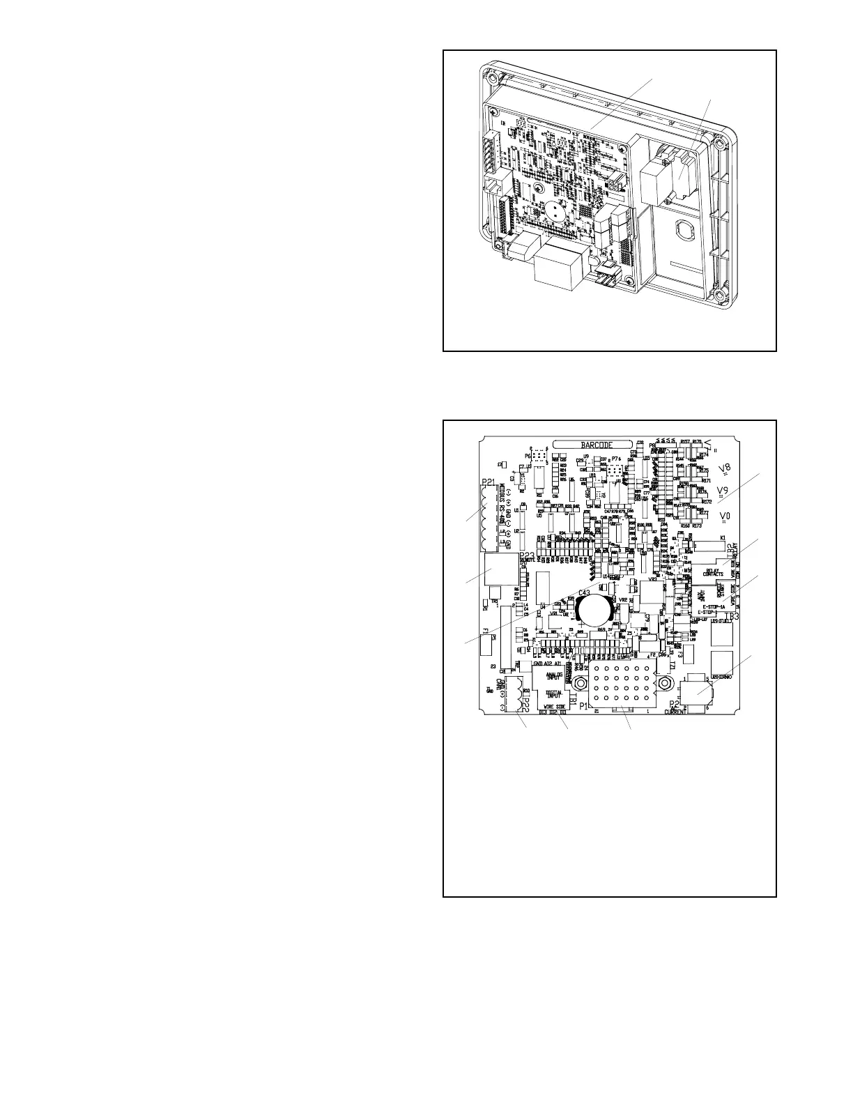
1. Main logic circuit board
2. Emergency stop switch
GM65741-
1
2
Figure 6-4 Main Circuit Board and Emergency Stop
Switch
1. (4) push-on terminal connectors
2. TB2 4-position terminal block
3. TB3 6-position terminal block
4. P2 6-pin connector
5. P1 24-pin connector
6. TB1 6-position terminal block
7. P22 3-pin connector
8. P30 jumper (Wound Field or Fast Response)
9. P23 8-pin connector (RJ45)
10. P21 6-pin connector (for RS-485 communications)
GM64345-C
4
5
67
9
10
3
1
2
8
Figure 6-5 Main Circuit Board Connectors

 Loading...
