2.
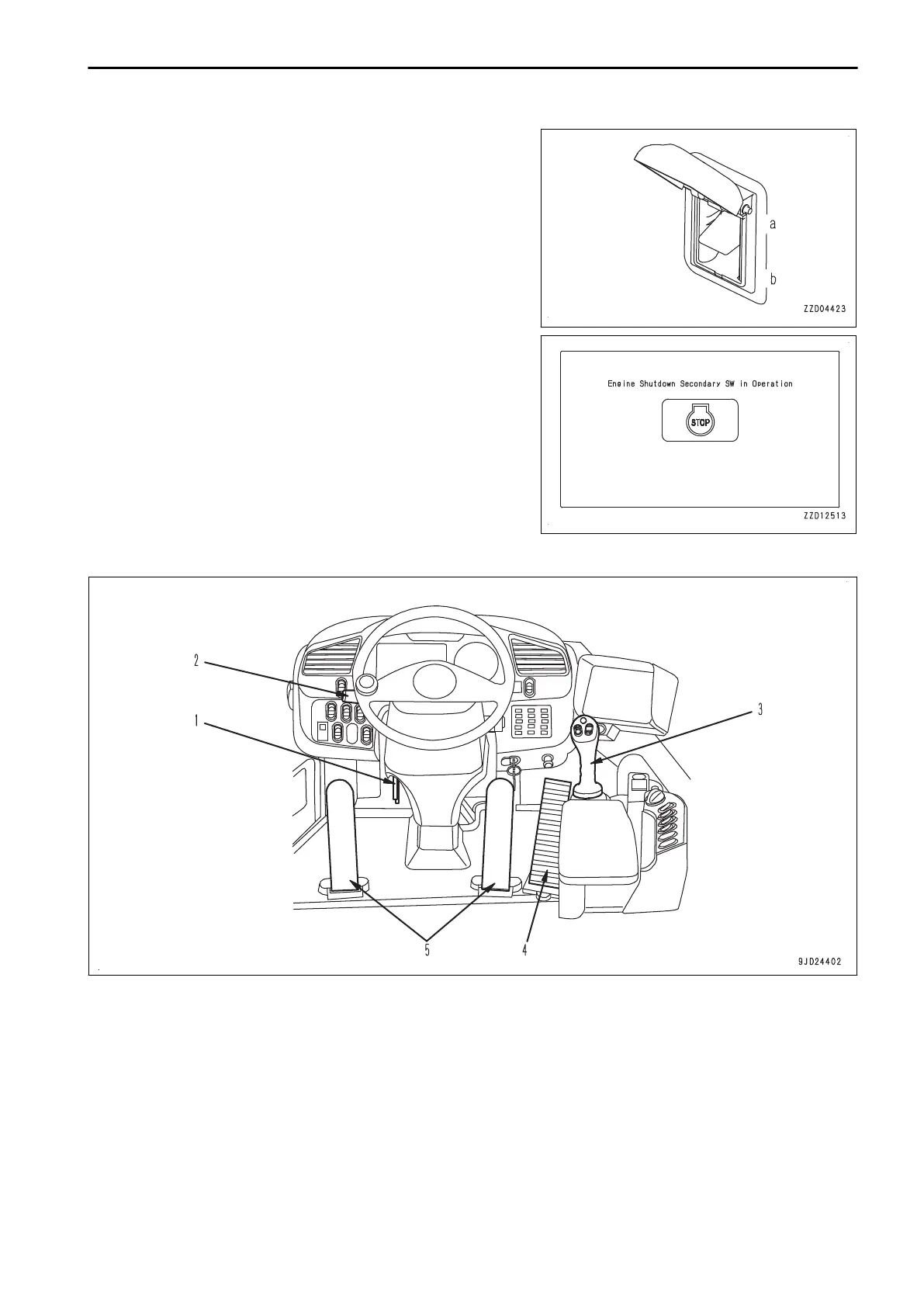
Pull up the switch, and the engine stops.
(a) STOP ENGINE: When abnormal (switch is set up)
(b) NORMAL: When normal (switch is set down)
• When cover (1)
is closed, the engine shutdown secon-
dary switch automatically returns to NORMAL position
(b).
• When the starting switch is turned to ON position
while the engine shutdown secondary switch is in
STOP ENGINE position (a), “Engine Shutdown Sec-
ondary SW in Operation” is displayed on the machine
monitor.
If this screen is displayed, return the engine shutdown
secondary switch to NORMAL position.
CONTROL LEVERS AND PEDALS
(1) Steering tilt lock lever
(2) Directional lever
(3) Multifunction mono-lever
(4) Accelerator pedal
(5) Brake pedal
OPERATION EXPLANATION OF COMPONENTS
3-107
 Loading...