11.
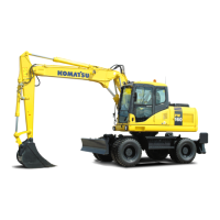
Check that the lock pin
indicators (3) on left and right side
are visible moved out.
12.
Check that the quick coupler and the attachment are com-
pletely locked.
13.
Release your hand from the quick coupler attachment
switch.
The switch returns to NEUTRAL position (N).
PRECAUTIONS FOR USING HYDRAULIC TYPE QUICK COUPLER
•
Check that the lock pin is securely inserted first, then operate the multifunction mono-lever.
• During the removal and installation of the attachment, the
notification of "Hydraulic Pressure Relief Event" may be
displayed on the monitor, however, it is not a problem.
(When the 3-point switch)
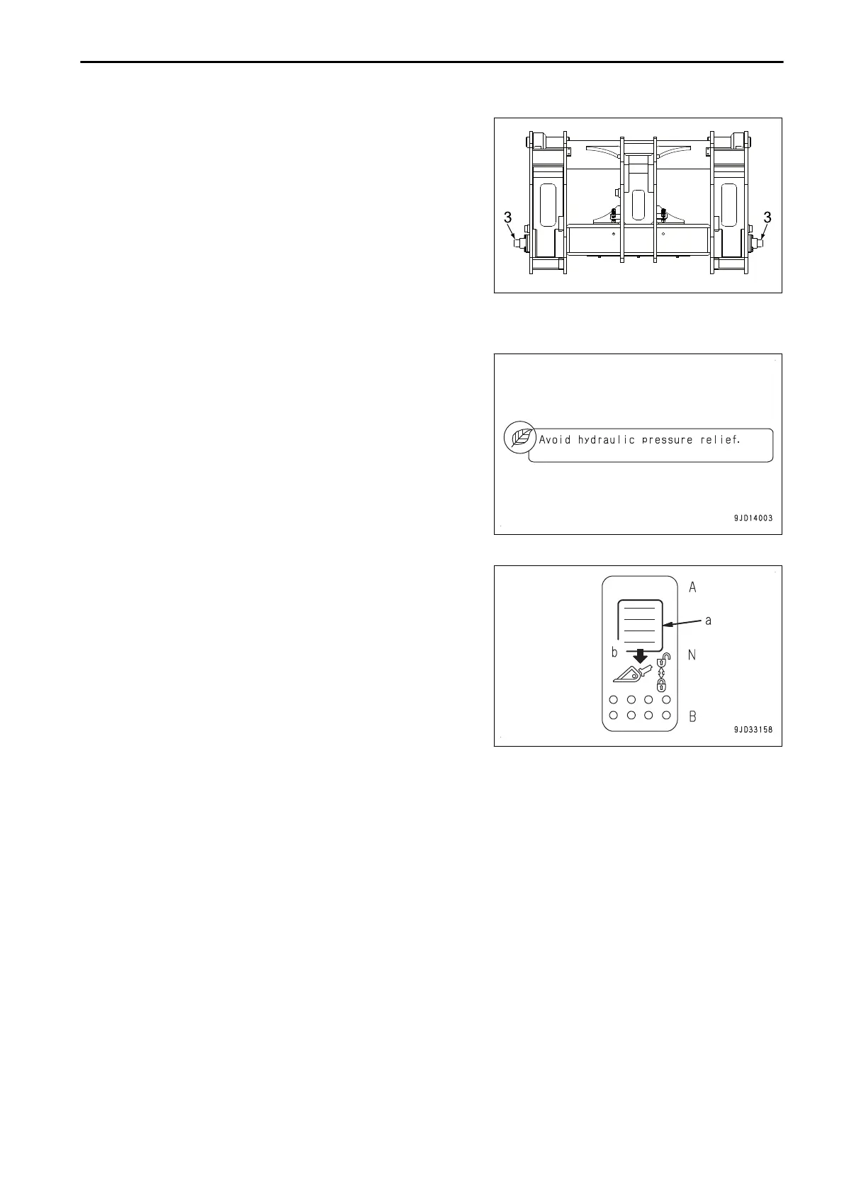
• The coupler plunger will be pulled out when the quick cou-
pler attachment switch is returned to NEUTRAL position
(N) from the decoupling position (A).
Before operating the attachment and work equipment,
push down the quick coupler attachment switch to the cou-
pling position (B) first, and check that the coupler plunger
is fully inserted.
ATTACHMENTS AND OPTIONS HANDLE HYDRAULIC TYPE QUICK COUPLER
6-23
 Loading...