16 TUNING THE ENGINE 95
16.8 Checking the basic position of the shift lever
Info
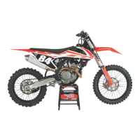
When driving, the shift lever must not touch the rider's boot when in the basic position.
When the shift lever keeps touching the boot, the transmission will be subject to an excessive load.
400692-10
–
Sit on the vehicle in the riding position and determine distance
between the
upper edge of your boot and the shift lever.
Distance between shift lever and upper
edge of boot
10… 20 mm (0.39… 0.79 in)
» If the distance does not meet specifications:
– Adjust the basic position of the shift lever. ( p. 95)
16.9 Adjusting the basic position of the shift lever
401950-12
–
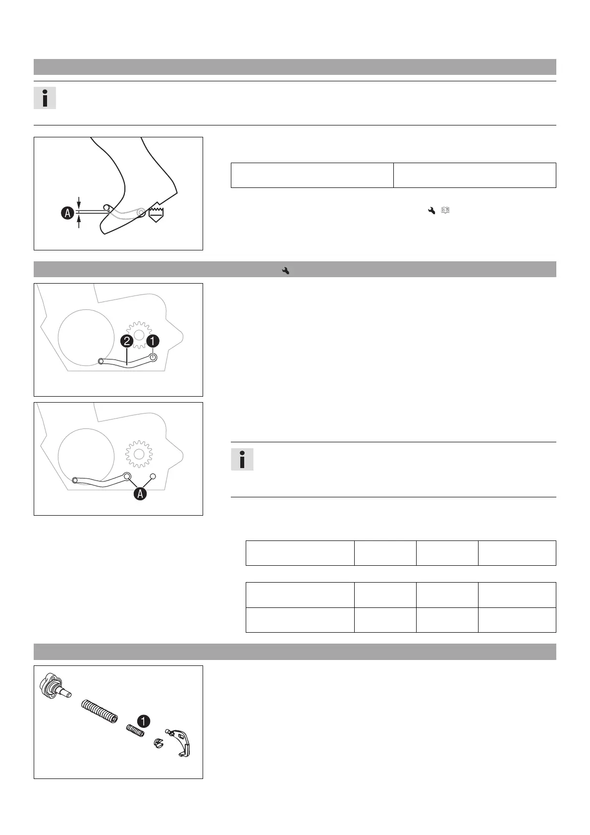
Remove screw
with washers and take off shift lever
.
401951-10
–
Clean gear teeth
of the shift lever and shift shaft.
– Mount the shift lever on the shift shaft in the required position and engage the
gearing.
Info
The range of adjustment is limited.
The shift lever must not come into contact with any other vehicle compo-
nents during the shift procedure.
–
Locate and tighten screw
with washers.
Guideline
(All 125/150 models)
Screw, shift lever M6 14 Nm
(10.3 lbf ft)
Loctite
®
243™
(All 250/300 models)
Screw, shift lever (All
250 SX models)
M6 14 Nm
(10.3 lbf ft)
Loctite
®
243™
Screw, shift lever (All XC
models)
M6 14 Nm
(10.3 lbf ft)
Loctite
®
243™
16.10 Engine characteristic – auxiliary spring (All 250/300 models)
B00056-10
The auxiliary spring is located on the right side of the engine below the water pump
cover.
Possible states
• Auxiliary spring with yellow marking – Auxiliary spring mounted at the factory with
medium tuning (standard) for good rideability.
• Auxiliary spring with green marking – Auxiliary spring for even softer performance.
• Auxiliary spring with red marking – Auxiliary spring for aggressive performance.
The engine characteristic can be influenced by different spring strengths of auxiliary
spring
.

 Loading...