TUNING THE CHASSIS 10
43
Info
Turn clockwise to increase the damping; turn counter-
clockwise to reduce damping when the shock absorber
rebounds.
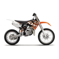
10.16 Handlebar position
C00248-10
On the upper triple clamp, there are 2 holes at a distance of
A
to
each other.
Hole distance A 15 mm (0.59 in)
The holes on the handlebar supports are placed at a distance
of
B
from the center.
Hole distance B 3.5 mm (0.138 in)
The handlebar supports can be mounted in four different posi-
tions. This allows the handlebar to be mounted in the most com-
fortable position for the rider.
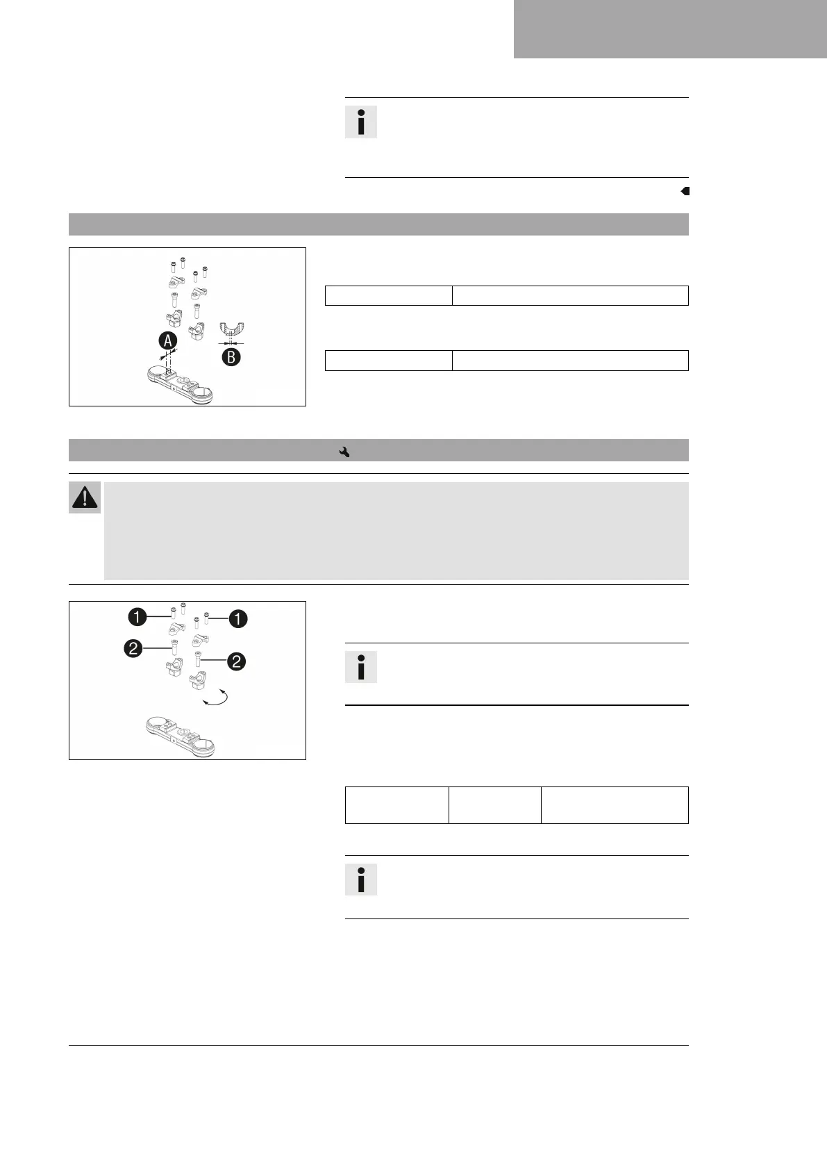
10.17 Adjusting the handlebar position
Warning
Danger of accidents A repaired handlebar poses a safety risk.
If the handlebar is bent or straightened, the material becomes fatigued. The handlebar may break as a
result.
– Change the handlebar if the handlebar is damaged or bent.
C00249-10
–
Remove screws
1
. Take off the handlebar clamps. Remove
the handlebar and lay it to one side.
Info
Cover the components to protect them against damage.
Do not kink the cables and lines.
–
Remove screws
2
. Take off the handlebar support.
– Place the handlebar support in the required position. Mount
and tighten screws
2
.
Guideline
Screw, handle-
bar support
M10 40 Nm (29.5 lbf ft)
Loctite
®
243™
– Position handlebar.
Info
Make sure the cables and wiring are positioned cor-
rectly.
–
Position handlebar clamps. Mount screws
1
and tighten
evenly.
 Loading...