Paragraphs 15-17
KUBOTA
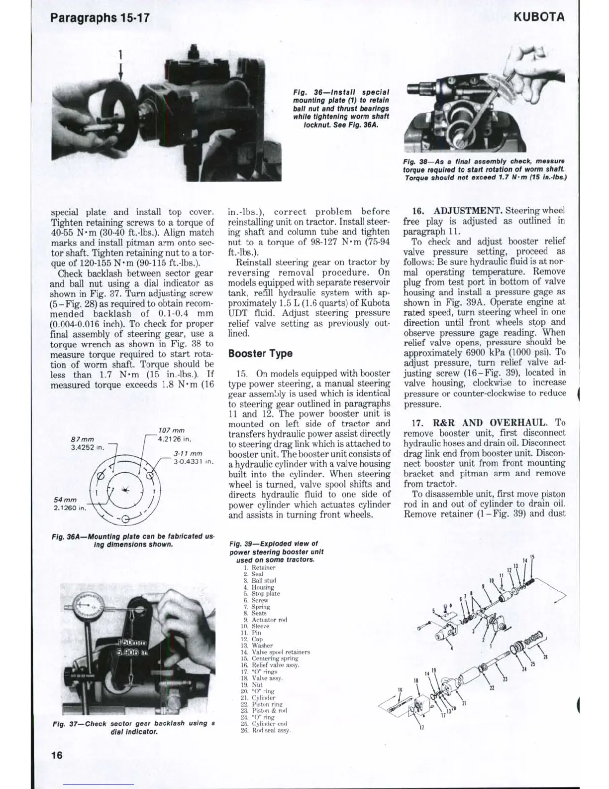
Fig. 36—Install speciai
mounting plate (1) to retain
ball nut and thrust bearings
while tightening worm shaft
tocknut See Fig. 36A.
Fig, 38—As a finai assembly check, measure
torque required to start rotation of worm shaft
Torque should not exceed 1.7 N-m (15 In.-lbs.)
special plate and install top cover.
Tighten retaining screws to a torque of
40-55 N-m (30-40 ft.-lbs.). Align match
marks and install pitman arm onto sec-
tor shaft. Tighten retaining nut to a tor-
que of 120-155 N-m (90-115 ft.-lbs.).
Check backlash between sector gear
and ball nut using a dial indicator as
shown in Fig. 37. Turn adjusting screw
(5-Fig. 28) as required to obtain recom-
mended backlash of 0.1-0.4 mm
(0.004-0.016 inch). To check for proper
final assembly of steering gear, use a
torque wrench as shown in Fig. 38 to
measure torque required to start rota-
tion of worm shaft. Torque should be
less than 1.7 N-m (15 in.-lbs.). If
measured torque exceeds 1.8 N-m (16
Ftg. 36A—Mounting plate can be fabricated us-
ing dimensions shown.
37—Check sector gear backlash using a
dtat Indicator.
in.-lbs.),
correct problem before
reinstalling unit on tractor. Install steer-
ing shaft and column tube and tighten
nut to a torque of 98-127 N-m (75-94
ft.-lbs.).
Reinstall steering gear on tractor by
reversing removal procedure. On
models equipped with separate reservoir
tank, refill hydraulic system with ap-
proximately 1.5 L (1.6 quarts) of Kubota
UDT fluid. Adjust steering pressure
relief valve setting as previously out-
lined.
Booster Type
15.
On models equipped with booster
type power steering, a manual steering
gear assembly is used which is identical
to steering gear outlined in paragraphs
11 and 12. The power booster unit is
mounted on left side of tractor and
transfers hydraulic power assist directly
to steering drag link which is attached to
booster unit. The booster unit consists of
a hydraulic cylinder with a valve housing
built into the cylinder. When steering
wheel is turned, valve spool shifts and
directs hydraulic fluid to one side of
power cylinder which actuates cylinder
and assists in turning front wheels.
Fig. 39—Exploded view of
power steering booster unit
used on some tractors.
1.
Retainer
2.
Seal
3.
Ball stud
4.
Housing
5.
Stop plate
6. Screw
7.
Spring
8. Seats
9. Actuator rod
10.
Sleeve
11.
Pin
12.
Cap
13.
Washer
14.
Valve spool retainers
15.
Centering spring
16.
Reliefvalve assy.
17.
"O" rings
18.
Valve assy.
19.
Nut
20.
"0" ring
. 21. Cylinder
22.
Piston ring
23.
Piston & rod
24.
"0" ring
25.
Cylinder end
26.
Rod seal assy.
16.
ADJUSTMENT. Steering wheel
free play is adjusted as outlined in
paragraph 11.
To check and adjust booster relief
valve pressure setting, proceed as
follows: Be sure hydraulic fluid is at nor-
mal operating temperature. Remove
plug from test port in bottom of valve
housing and install a pressure gage as
shown in Fig. 39A. Operate engine at
rated speed, turn steering wheel in one
direction until front wheels stop and
observe pressure gage reading. When
relief valve opens, pressure should be
approximately 6900 kPa (1000 psi). To
adjust pressure, turn relief valve ad-
justing screw (16-Fig. 39), located in
valve housing, clockwise to increase
pressure or counter-clockwise to reduce
pressure.
17.
R&R AND OVERHAUL. To
remove booster unit, first disconnect
hydraulic hoses and drain oil. Disconnect
drag link end from booster unit. Discon-
nect booster unit from front mounting
bracket and pitman arm and remove
from tractor.
To disassemble unit, first move piston
rod in and out of cylinder to drain oil.
Remove retainer (1-Fig. 39) and dust
16
 Loading...


