SHOP MANUAL
air-free fuel appears, then tighten vent
plug.
If engine fails
to
start after bleeding
air from filter
and
pump, loosen high
pressure line connections
at
injector
nozzles. Move throttle
to run
position
and crank engine with starting motor
until fuel appears
at
loosened injector
line fittings. Tighten fittings
and
start
engine.
INJECTION PUMP
A Bosch
K
type pump
is
used
on all
models. The injection pump
is a
complete-
ly sealed unit
and no
service work
or
disassembly other than that specified
should
be
attempted without necessary
special equipment
and
training.
All Models
46.
TIMING
TO
ENGINE.
On all
models, start
of
injection should occur
at
25° BTDC.
To check timing, disconnect fuel
pressure line from injection pump front
delivery valve holder. Place throttle con-
trol
in
maximum fuel position
and
pull
decompressor knob
out.
Turn
crankshaft slowly until wetness appears
at discharge fitting
of
injection pump.
At this point (beginning
of
injection),
"FI"
mark on fiywheei should be aligned
with timing check window.
If timing requires adjustment, remove
shims (Fig. 59) between injection pump
mounting flange
and
cylinder block
to
advance timing
or
add
shims
to
retard
timing. Adding
or
removing
one
shim
will change timing about
1V2
crankshaft
degrees which
is
about
2.3
mm (3/32
inch) measured
on
flywheel
rim.
47.
REMOVE AND REINSTALL.
To remove injection pump, first
thoroughly clean outside
of
pump
and
surrounding area. Shut
off
fuel
and
disconnect fuel supply line
at
injection
pump. Remove high pressure lines
leading
to
injectors. Remove side access
cover
or
engine stop lever assembly
if
so
equipped. Remtwe pump mounting stud
Paragraphs 46-47
Injection timing
adjusting shim
(o
Fig. 59—Injection pump timing
is
adjusted
by
adding
or
removing pump mounting shims. Ad-
ding
or
removing
one
shim wiii change timing
about
IVz
crankshaft degrees.
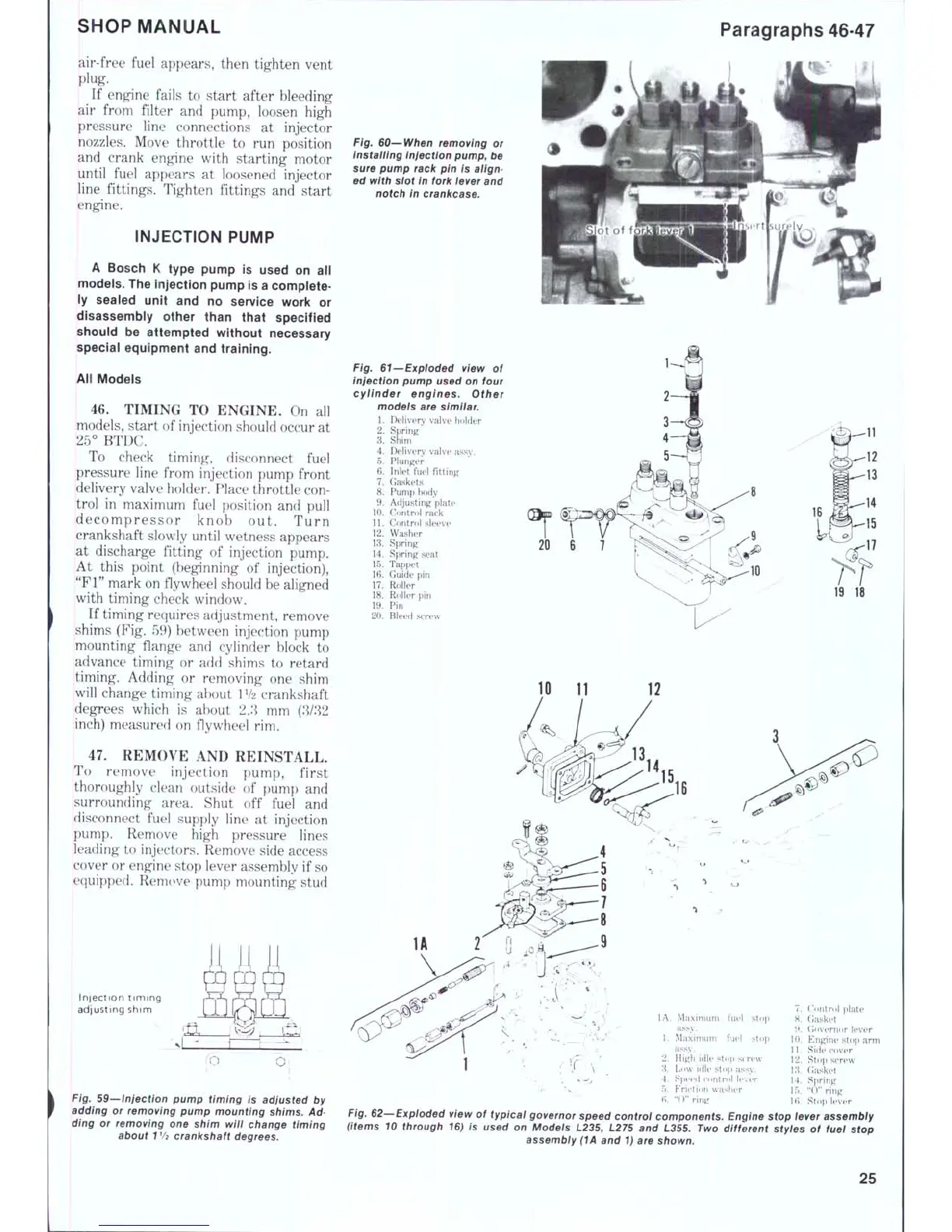
Fig. 60—When removing
or
installing injection pump, be
sure pump rack pin
is
align-
ed with slot in fork iever and
notch
in
crankcase.
Fig. 61—Expioded view
of
injection pump used on four
cyiinder engines. Other
modeis
are
similar.
1.
Delivery valve holder
2.
Spring
^
3.
Shim
4.
Delivery valve assy.
5.
Plunger
6. Inlet fuel fitting
7.
Gaskets
8. Pump body
9. Adjusting plate
10.
Control rack
11.
Control sleeve
12.
Washer
13.
Spring
14.
Spring seat
15.
Tappet
16.
Guide
pin
17.
Roller
18.
Roller
pin
19.
Pin
20.
Bleed screw
19
18
10
11
i'uvl
fuel
;top
^top
'W
7.
H.
i>.
U).
11.
12.
Control plate
Gasket
Governor lever
Engine stop
arm
Side cover
Stop screw
Gasket
lA.
Maximum
assy.
1.
Maximum
as.sy.
2.
High idle stof)
s{
n
8.
Low
idle stop assy
•
. ; ^-0 ' 4.
Speed controi levi'r
14.
Spring
->
"v_ ' 5.
Friction waslier
15.
"0"
ring
f^- "<>" ring
IB,
Stf>p lever
Fig. 62—Expioded view
of
typicai governor speed control components. Engine stop iever assembiy
(items
10
through 16)
is
used
on
Models L235, L275
and
L355. Two different styles
of
fuel stop
assembly (1A
and
1) are shown.
25
 Loading...


