Paragraphs 121-122
KUBOTA
gear (7) from body and separate com-
ponents as shown. Be sure to identify
bushings (5) so they can be reinstalled in
their original positions. Drive oil seal
(10) out of body (9).
To disassemble front pump, remove
adapter plate (13-Fig. 162) and center
plate (15) on tandem pumps. On single
' pump, remove end cover (25-Fig. 163).
On all models, push gears and bushings
from body. Identify bushings so they can
be reinstalled in their original positions.
Drive oil seal
(24
-
Fig.
162 or 163) out of
mounting flange (23). Discard all "0"
rings and seal rings.
Inspect all parts for excessive wear,
scoring or other damage. Inside
diameter of pump body should not ex-
ceed 39.575 mm (1.558 inches) on front
pump and 31.088 mm (1.2239 inches) on
rear pump. Clearance between bushings
and gear shafts should not exceed 0.188
mm (0.0074 inch) on front pump and
0.177 mm (0.0069 inch) on rear pump
section. Minimum allowable bushing
length is 18.92 mm (0.745 inch) on front
pump and 18.67 mm (0.735 inch) on rear
pump. Renew all "0" rings and seal
rings.
When reassembling pump sections,
lubricate all parts with clean hydraulic
oil.
Tighten center plate (15) mounting
cap screws to a torque of 46-49 N-m
(34-36 ft.-lbs.) Tighten adapter plate (13)
mounting screws to a torque of 26-32
N-m (19-24 ft.-lbs.). Tighten rear pump
end cover (1) cap screws to a torque of
26-32 N-m (19-24 ft.-lbs.).
Reinstall pumps and connect
discharge hydraulic pipes. Fill pump
bodies with clean hydraulic oil, then con-
nect inlet pipes.
HYDRAULIC VALVES
All Models
121.
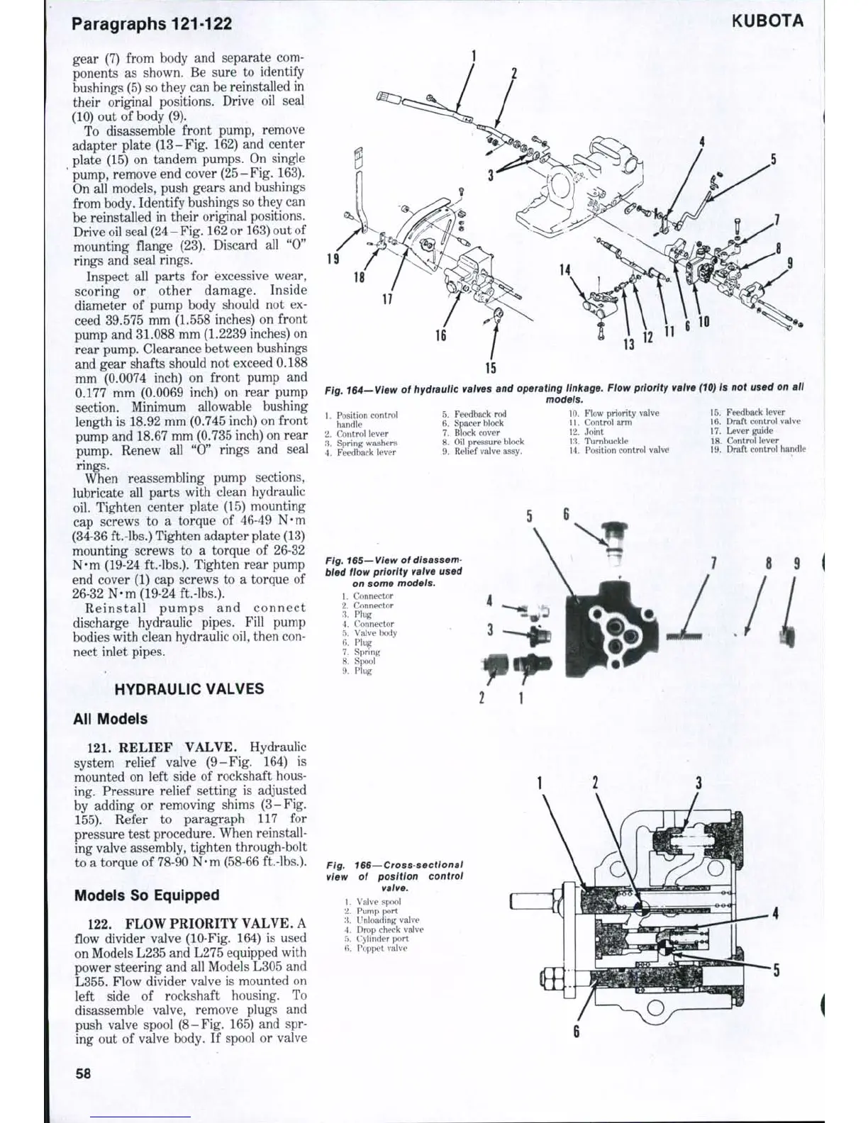
RELIEF VALVE. Hydraulic
system relief valve (9-Fig. 164) is
mounted on left side of rockshaft hous-
ing. Pressure relief setting is adjusted
by adding or removing shims (3-Fig.
155).
Refer to paragraph 117 for
pressure test procedure. When reinstall-
ing valve assembly, tighten through-bolt
to a torque of 78-90 N-m (58-66 ft.-lbs.).
Models So Equipped
122.
FLOW PRIORITY VALVE. A
flow divider valve (10-Fig. 164) is used
on Models L235 and L275 equipped with
power steering and all Models L305 and
L355.
Flow divider valve is mounted on
left side of rockshaft housing. To
disassemble valve, remove plugs and
push valve spool (8-Fig. 165) and spr-
ing out of valve body. If spool or valve
13
, 164—View of hydraulic valves and operating linkage. Flow priority valve (TO/ Is not used on alt
models.
5.
Feedback rod 10. Flow priority valve 15. Feedback lever
6. Spacer block 11. Control arm 16. Draft control valve
7.
Block cover 12. Joint 17. Lever guide
1.
Position control
handle
2.
Control lever
;i.
Spring washers
4.
Feedback lever
8. Oil pressure block
9. Relief valve assy.
13.
Turnbuckle
14.
Position control valve
18.
Control lever
19.
Draft control handle
5
6
Fig. 165—View of disassem-
bled flow priority valve used
on some models.
1.
Connector
2.
Connector
3.
Plug
4.
('onnector
T).
Valve body
6. Plug
7.
Spring
8. SfKJol
9. Plug
8
9
Fig. 166—Cross sectionai
view of position controi
valve.
1.
V a l v e s|MK>l
2.
Pump port
'.\. Unloading valve
4.
Drop check valve
5.
Cylinder port
fi. F^oppet valve
58
 Loading...


