SHOP MANUAL
Paragraph 116
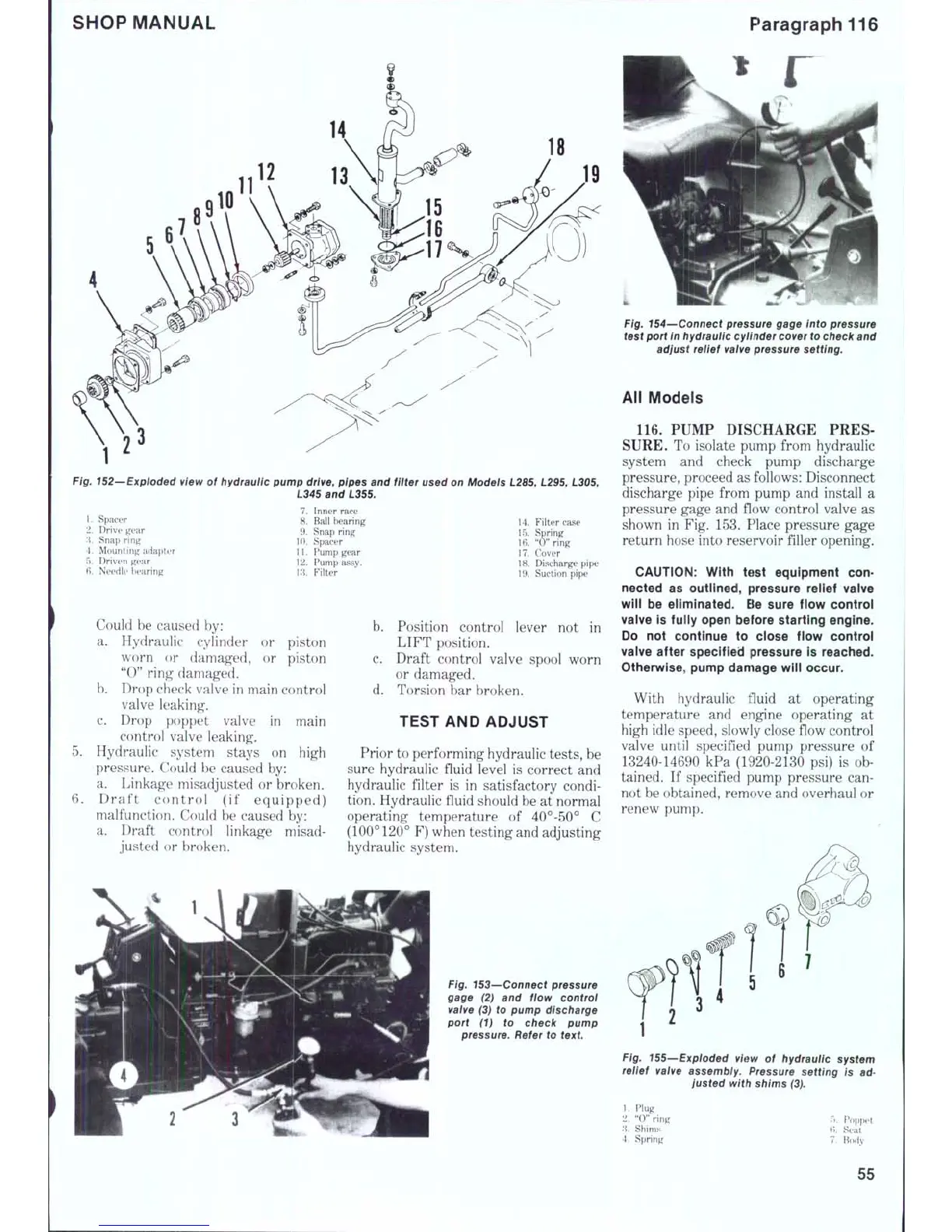
Fig. 152—Exploded view
of
hydraulic pump drive, pipes and filter used on Models L285, L295, L305,
L345 and L355.
1,
Spacer
2.
Drive
'\. Snap
r
4.
Mounti
T).
Driven
6, Needk' bearing
adapter
7.
Inner race
8. Ball bearing
9. Snap ring
10.
Spacer
11.
Pump gear
12.
Pump assy.
13.
Filter
Could
be
caused
by:
a. Hydraulic cylinder
or
piston
worn
or
damaged,
or
piston
"0"
ring damaged.
b.
Drop check valve in main control
valve leaking.
c. Drop poppet valve
in
main
control valve leaking.
Hydraulic system stays
on
high
pressure. Could
be
caused
by:
a. Linkage misadjusted
or
broken.
Draft control
(if
equipped)
malfunction. Could
be
caused
by:
a. Draft control linkage misad-
justed
or
broken.
c.
d.
14.
Filter case
15.
Spring
16.
"0" ring
17.
Cover
18.
Discharge pipe
19.
Suction pipe
Position control lever
not in
LIFT position.
Draft control valve spool worn
or damaged.
Torsion
bar
broken.
TEST AND ADJUST
Prior to performing hydraulic tests,
be
sure hydraulic fluid level
is
correct
and
hydraulic filter
is in
satisfactory condi-
tion. Hydraulic fluid should be
at
normal
operating temperature
of
40°-50°
C
(100° 120°
F) when testing and adjusting
hydraulic system.
Fig. 153—Connect pressure
gage
(2) and
flow control
valve
(3) to
pump discharge
port
(1) to
check pump
pressure. Refer
to
text
Fig. 154~~Connect pressure gage into pressure
test port in hydraulic cylinder cover to check and
adjust relief valve pressure setting.
All Models
116.
PUMP DISCHARGE PRES-
SURE.
To
isolate pump from hydraulic
system
and
check pump discharge
pressure, proceed as follows: Disconnect
discharge pipe from pump
and
install
a
pressure gage and flow control valve
as
shown
in
Fig. 153. Place pressure gage
return hose into reservoir filler opening.
CAUTION:
With test equipment con-
nected as outlined, pressure relief vaive
will be eliminated. Be sure flow control
valve is fuiiy open before starting engine.
Do not continue to close flow controi
valve after specified pressure is reached.
Otherwise, pump damage will occur.
With hydraulic fluid
at
operating
temperature
and
engine operating
at
high idle speed, slowly close flow control
valve until specified pump pressure
of
13240-14690
kPa
(1920-2130
psi) is ob-
tained.
If
specified pump pressure
can-
not be obtained, remove and overhaul
or
renew pump.
Fig. 155—Exploded view
of
hydraulic system
reiief valve assembiy. Pressure setting
is ad-
justed with shims (3).
1.
Plug
2. "0"
ring
.'{.
Shims
4.
Spring
r.. Poppet
(i.
Seat
7.
Body
55
 Loading...


