SHOP MANUAL
transmission housings, then remove
mounting stud nuts
and
separate hous-
ings.
When reconnecting tractor, tighten
housing mounting stud nuts
to a
torque
of 103-118
N-m
(76-86 ft.-lbs.), clutch
housing mounting bolts
to
78-90
N*m
(57-66 ft.-lbs.)
and
engine mounting
bolts
to a
torque
of
49-56
N-m
(36-41
ft.-lbs.)
Be
sure "0" rings
are
correctly
positioned when reinstalling hydraulic
pipes.
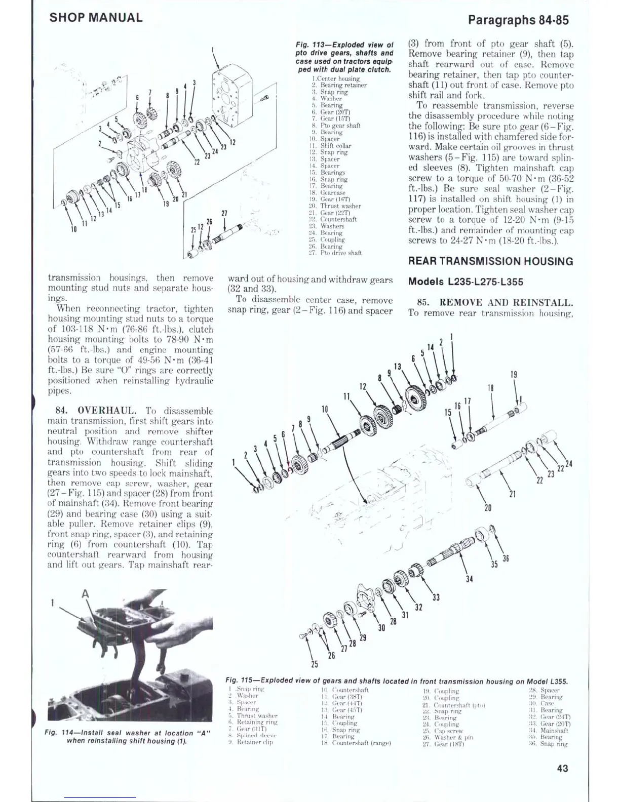
84.
OVERHAUL.
To
disassemble
main transmission, first shift gears into
neutral position
and
remove shifter
housing. Withdraw range countershaft
and
pto
countershaft from rear
of
transmission housing. Shift sliding
gears into two speeds
to
lock mainshaft,
then remove
cap
screw, washer, gear
(27
-
Fig.
115) and spacer (28) from front
of mainshaft (34). Remove front bearing
(29)
and
bearing case
(30)
using
a
suit-
able puller. Remove retainer clips
(9),
front snap ring, spacer
(3),
and retaining
ring
(6)
from countershaft
(10). Tap
countershaft rearward from housing
and lift
out
gears.
Tap
mainshaft rear-
Fig. 113—Exploded view of
pto drive gears, shafts and
case used on tractors equip-
ped witfi dual plate clutch.
1
.Center housing
2.
Bearing retainer
3.
Snap ring
4.
Washer
5.
Bearing
6. Gear
(20T)
7.
Gear(15T)
8.
Pto
gear shaft
9. Bearing
10.
Spacer
11.
Shift collar
12.
Snap ring
13.
Spacer
14.
Spacer
15.
Bearings
16.
Snap ring
17.
Bearing
18.
Gearcase
19.
Gear
(16T)
20.
Thrust washer
21.
Gear(22T)
22.
Countershaft
23.
Washers
24.
Bearing
25.
Coupling
26.
Bearing
27.
Pto
drive shaft
ward out
of
housing and withdraw gears
(32
and
33).
To disassemble center case, remove
snap ring, gear (2-Fig. 116) and spacer
Paragraphs 84-85
(3) from front
of pto
gear shaft
(5).
Remove bearing retainer
(9),
then
tap
shaft rearward
out of
case. Remove
bearing retainer, then
tap pto
counter-
shaft (11)
out
front
of
case. Remove
pto
shift rail
and
fork.
To reassemble transmission, reverse
the disassembly procedure while noting
the following:
Be
sure
pto
gear
(6
-
Fig.
116) is installed with chamfered side
for-
ward. Make certain oil grooves
in
thrust
washers (5-Fig. 115)
are
toward splin-
ed sleeves
(8).
Tighten mainshaft
cap
screw
to a
torque
of
50-70
N-m
(36
52
ft.-lbs.)
Be
sure seal washer (2-Fig.
117)
is
installed
on
shift housing
(1)
in
proper location. Tighten seal washer cap
screw
to a
torque
of
12-20
N-m
(9-15
ft.-lbs.)
and
remainder
of
mounting
cap
screws
to
24-27 N-m (18-20 ft.-lbs.).
REAR TRANSMISSION HOUSING
Models L235-L275-L355
85.
REMOVE
AND
REINSTALL.
To remove rear transmission housing.
36
Fig. 115—Exploded view of gears and shafts located in front transmission housing on Model
L355.
Fig. 114—instaif seai washer at iocation
when reinstailing shift housing (1).
1 .Snap
f^
2
.Washer
.'i,
Sftacer
4.
Bearing
5.
Thrust washer
6. Retaining ring
7.
Gear(;ilT)
8. Splined sleeve
9. Retainer clip
]().
Co un te rs ha ft
12.
(iear(44T)
\:i Gear{45T)
14.
Bearing
IT),
('oupiing
IB.
Snap ring
17.
Bearing
18.
Counters haft (range)
19.
Cnu[)ling
20.
Coupling
21.
Countershaft
(pto)
ZZ.
bnap ring
2'J. Bearing
24.
Coupling
25.
Cap
screw
26.
Washer
& pin
27.
GeardHT)
28.
Spacer
2V>.
Bearing
;iO.
Case
'.l\.
Bearing
H2.
Gear(24T)
XI
Gear(20T)
'M.
Mainshaft
;{;").
Bearing
'J6.
Snap ring
43
 Loading...


