Paragraph 73
KUBOTA
34
36
1.
Reverse idler shaft
2.
Set screw
3.
Bushings
4.
Reverse idler gear
5.
Cover
6. Snap ring
7.
Bearing
8. Thrust washer
9. Retaining ring
10.
Gear(32T)
11.
Spline boss
12.
Retainer clip
13.
Gear(41T)
14.
Countershaft
15.
Gear(45T)
16.
Gear(45T)
17.
Bearing
18.
Washer
20.
Oil seal
21.
Snap ring
22.
Washer
23.
Bearing
24.
Gear(23T)
25.
Gear(17T)
26.
Input shaft
27.
Washer
28.
Snap ring
29.
Bearing
30.
Washer
31.
Spacer
32.
Washer
&
dowel pin
33.
Washer
34.
Cap screw
35.
Cover
36.
Snap ring
37.
Washer
38.
Bearing
39.
Spacer
40.
Gear(41T)
41.
Pto countershaft
42.
Gear(45T)
43.
Retainer clip
44.
Spline boss
45.
Gear(45T)
46.
Thrust washer
47.
Bearing
48.
Washer
49.
Spring
50.
Pto clutch cams
51.
Snap ring
52.
Spacer
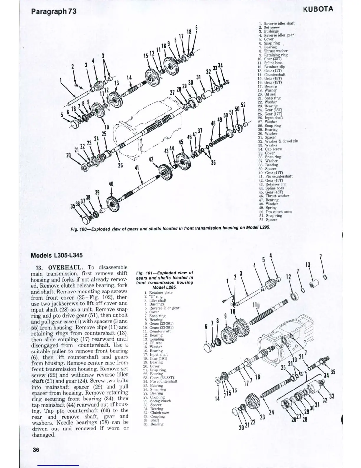
Fig. 100—Explod9d Wew of gears and shafts located in front transmission housing on Model L29S.
Models L305-L345
73.
OVERHAUL. To disassemble
main transmission, first remove shift
housing and forks if not already remov-
ed. Remove clutch release bearing, fork
and shaft. Remove mounting cap screws
from front cover (25-Fig, 102), then
use two jackscrews to lift off cover and
input shaft (28) as a unit. Remove snap
ring and pto drive gear (51), then unbolt
and pull gear case (1) with spacers
(3
and
55) from housing. Remove clips (11) and
retaining rings from countershaft (13),
then slide coupling (17) rearward until
disengaged from countershaft. Use a
suitable puller to remove front bearing
(6),
then lift countershaft and gears
from housing. Remove center case from
front transmission housing. Remove set
screw (22) and withdraw reverse idler
shaft (21) and gear
(24).
Screw two bolts
into mainshaft spacer (29) and pull
spacer from housing. Remove retaining
ring securing front bearing (34), then
tap mainshaft (44) rearward out of hous-
ing. Tap pto countershaft (60) to the
rear and remove shaft, gear and
washers. Needle bearings (58) can be
driven out and renewed if worn or
damaged.
Fig. 101—Exploded view of
gears and shafts located in
front transmission housing
Model L285.
1.
Retainer plate
2.
"0" ring
3.
Idler shaft
4.
Bushings
5.
Reverse idler gear
6. Cover
7.
Snap ring
8. Bearing
9. Gears (23 36T)
10.
Gears (33-38T)
11.
Countershaft
12.
Bearing
13.
Coupling
14.
Oil seal
15.
Washer
16.
Bearing
17.
Input shaft
18.
Gear(19T)
19.
Bearing
20.
Cover
21.
Snap ring
22.
Bearing
23.
Gears (33-38T)
24.
Pto c_ountershaft
25.
Bearing
26.
Snap ring
27.
Bearing
28.
Coupling
29.
Sprag clutch
30.
Spacer
31.
Bearing
32.
Clutch case
33.
Coupling
34.
Shaft
35.
Bearing
26^28
36
 Loading...


