Paragraphs 32-34
in end of fuel camshaft. Complete
reassembly by reversing disassembly
procedure.
TIMING GEARS
All Models
32.
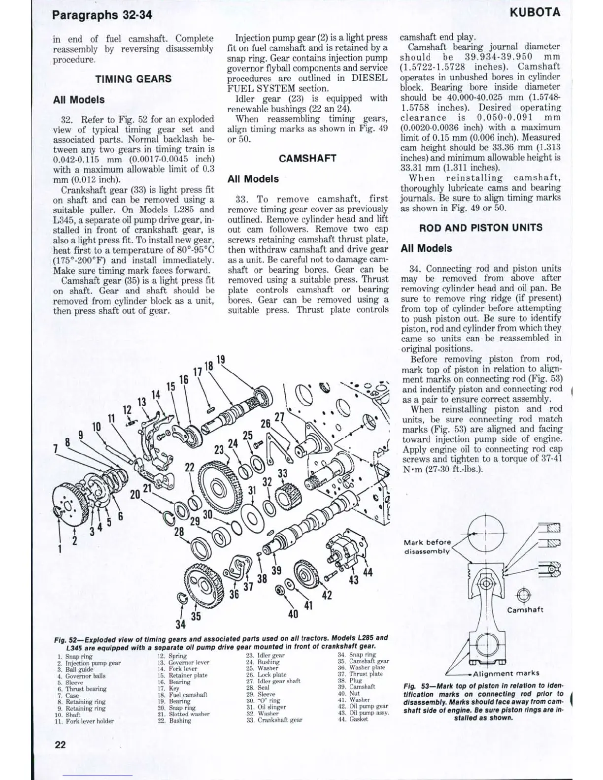
Refer to Fig. 52 for an exploded
view of typical timing gear set and
associated parts. Normal backlash be-
tween any two gears in timing train is
0.042-0.115 mm (0.0017-0.0045 inch)
with a maximum allowable limit of 0.3
mm (0.012 inch).
Crankshaft gear (33) is light press fit
on shaft and can be removed using a
suitable puller. On Models L285 and
L345,
a separate oil pump drive gear, in-
stalled in front of crankshaft gear, is
also a light press fit. To install new gear,
heat first to a temperature of 80°-95°C
(175°-200°F) and install immediately.
Make sure timing mark faces forward.
Camshaft gear (35) is a light press fit
on shaft. Gear and shaft should be
removed from cylinder block as a unit,
then press shaft out of gear.
Injection pump gear (2) is a light press
fit on fuel camshaft and is retained by a
snap ring. Gear contains injection pump
governor fiyball components and service
procedures are outlined in DIESEL
FUEL SYSTEM section.
Idler gear (23) is equipped with
renewable bushings (22 an 24).
When reassembling timing gears,
align timing marks as shown in Fig. 49
or 50.
CAMSHAFT
All Models
33.
To remove camshaft, first
remove timing gear cover as previously
outlined. Remove cylinder head and lift
out cam followers. Remove two cap
screws retaining camshaft thrust plate,
then withdraw camshaft and drive gear
as a unit. Be careful not to damage cam-
shaft or bearing bores. Gear can be
removed using a suitable press. Thrust
plate controls camshaft or bearing
bores.
Gear can be removed using a
suitable press. Thrust plate controls
40
Fig. 52—Expioded view of timing gears and associated parts used on all tractors. Modeis L285 and
L345 are equipped with a separate oil pump drive gear mounted in front of crankshaft
gear.
12.
Spring 23. Idler gear 34. Snap ring
13.
Governor lever 24. Bushing 35. Camshaft gear
14.
Fork lever 25. Washer 36. Washer plate
15 Retainer plate 26. Lcwk plate 37. Thrust plate
16.
Bearing 27. Idler gear shaft 38. Plug
17.
Key 28. Seal 39. Camshaft
18.
Fuel camshaft 29. Sleeve 40. Nut
19 Bearing 30. "0" ring 41. Washer
20.
Snap ring 31. Oil slinger 42. Oil pump gear
21.
Slotted washer 32. Washer 43. Oil pump assy.
22.
Bushing 33. Crankshaft gear 44. Gasket
1.
Snap ring
2.
Injection pump gear
3.
Ball guide
4.
Governor balls
5.
Sleeve
6. Thrust bearing
7.
Case
8. Retaining ring
9. Retaining ring
10.
Shaft
11.
Fork lever holder
KUBOTA
camshaft end play.
Camshaft bearing journal diameter
should be 39.934-39.950 mm
(1.5722-1.5728 inches). Camshaft
operates in unbushed bores in cylinder
block. Bearing bore inside diameter
should be 40.000-40.025 mm (1.5748-
1.5758
inches). Desired operating
clearance is 0.050-0.091 mm
(0.0020-0.0036 inch) with a maximum
limit of 0.15 mm (0.006 inch). Measured
cam height should be 33.36 mm (1.313
inches) and minimum allowable height is
33.31 mm (1.311 inches).
When re inst alli ng camshaft,
thoroughly lubricate cams and bearing
journals. Be sure to align timing marks
as shown in Fig. 49 or 50.
ROD AND PISTON UNITS
All Models
34.
Connecting rod and piston units
may be removed from above after
removing cylinder head and oil pan. Be
sure to remove ring ridge (if present)
from top of cylinder before attempting
to push piston out. Be sure to identify
piston, rod and cylinder from which they
came so units can be reassembled in
original positions.
Before removing piston from rod,
mark top of piston in relation to align-
ment marks on connecting rod (Fig. 53)
and indentify piston and connecting rod
as a pair to ensure correct assembly.
When reinstalling piston and rod
units,
be sure connecting rod match
marks (Fig. 53) are aligned and facing
toward injection pump side of engine.
Apply engine oil to connecting rod cap
screws and tighten to a torque of 37-41
N-m (27-30 ft.-lbs.).
Mark before
disassembly
Alignment marks
Fig. 53—Mark top of piston in reiation to iden-
tification marks on connecting rod prior to
disassembly. Marks shouid face away from cam-
shaft side of engine. Be sure piston rings are in-
staiied as shown.
22
 Loading...


