SHOP MANUAL
Paragraphs 123-125
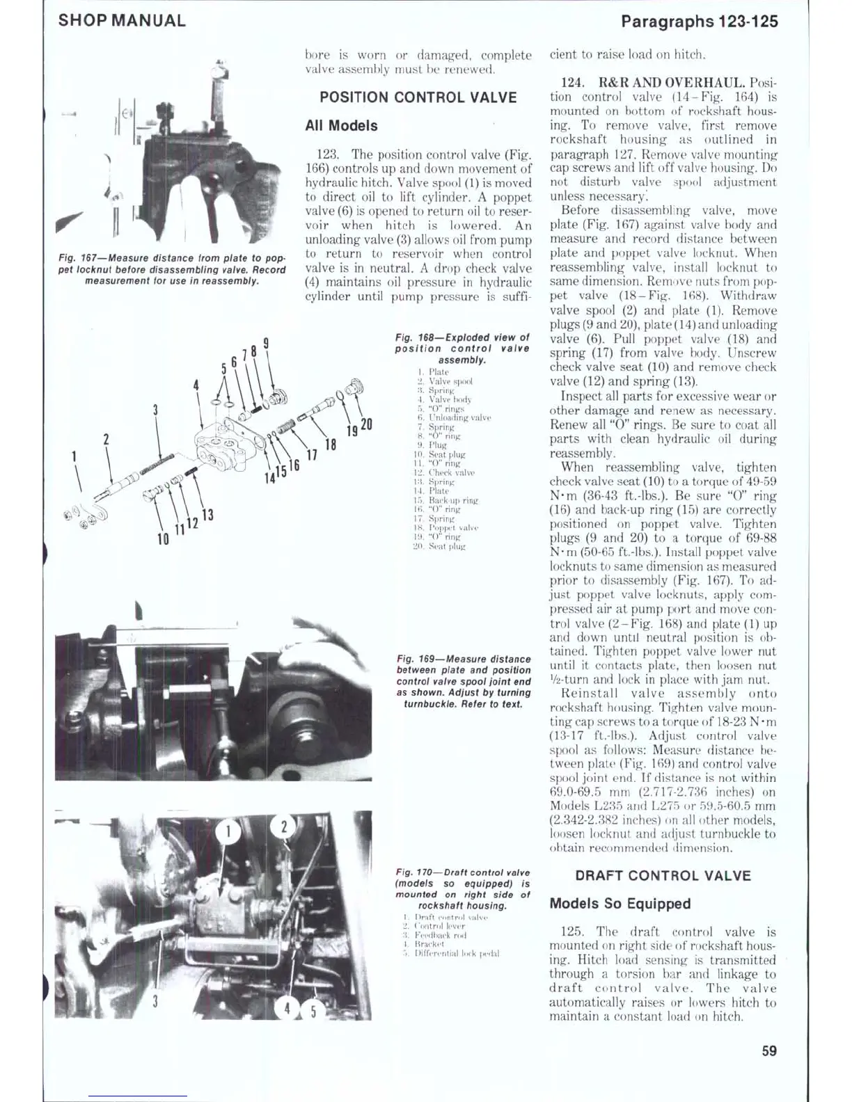
Fig. 167—Measure distance from plate to pop-
pet locknut before disassembling valve. Record
measurement for use In reassembly.
bore is worn or damaged, complete
valve assembly must be renewed.
POSITION CONTROL VALVE
All Models
123.
The position control valve (Fig.
166) controls up and down movement of
hydraulic hitch. Valve spool (1) is moved
to direct oil to lift cylinder. A poppet
valve (6) is opened to return oil to reser-
voir when hitch is lowered. An
unloading valve (3) allows oil from pump
to return to reservoir when control
valve is in neutral. A drop check valve
(4) maintains oil pressure in hydraulic
cylinder until pump pressure is suffi-
Fig.
168—Exploded
view
of
position controi valve
1.
2
'I.
4,
5.
6.
7.
8,
9.
10.
11.
12.
i:i
14.
15.
16.
17.
18.
19.
20.
assembiy.
Plate
V'alve spool
Spring
Valve body
"0"
rings
Unloading valve
Spring
"0"
ring
Plug
Seat plug
"0"
ring
Check valve
Spring
Plate
Back-up ring
"0"
ring
Spring
Poppet valve
"0"
ring
Seat plug
Fig. 169—Measure distance
between pi ate and position
controi vaive spool joint end
as shown. Adjust by turning
turnbuckle. Refer to
text.
Fig. 170—Draft control valve
(models so equipped) is
mounted on right side of
rockshaft housing.
1.
Draft control valve
2.
Control lever
:{.
Feedback rod
4.
Bracket
.'>.
Differential lock perlal
cient to raise load on hitch.
124.
R&R AND OVERHAUL. Posi-
tion control valve (14-Fig. 164) is
mounted on bottom of rockshaft hous-
ing. To remove valve, first remove
rockshaft housing as outlined in
paragraph 127. Remove valve mounting
cap screws and lift off valve housing. Do
not disturb valve spool adjustment
unless necessary.
Before disassembling valve, move
plate (Fig. 167) against valve body and
measure and record distance between
plate and poppet valve locknut. When
reassembling valve, install locknut to
same dimension. Remove nuts from pop-
pet valve (18-Fig. 168). Withdraw
valve spool (2) and plate (1). Remove
plugs (9 and 20), plate (14) and unloading
valve (6). Pull poppet valve (18) and
spring (17) from valve body. Unscrew
check valve seat (10) and remove check
valve (12) and spring (13).
Inspect all parts for excessive wear or
other damage and renew as necessary.
Renew all "0" rings. Be sure to coat all
parts with clean hydraulic oil during
reassembly.
When reassembling valve, tighten
check valve seat (10) to a torque of 49-59
N-m (36-43 ft.-lbs.). Be sure "0" ring
(16) and back-up ring (15) are correctly
positioned on poppet valve. Tighten
plugs (9 and 20) to a torque of 69-88
N*m (50-65 ft.-lbs.). Install poppet valve
locknuts to same dimension as measured
prior to disassembly (Fig. 167). To ad-
just poppet valve locknuts, apply com-
pressed air at pump port and move con-
trol valve (2-Fig. 168) and plate (1) up
and down until neutral position is ob-
tained. Tighten poppet valve lower nut
until it contacts plate, then loosen nut
V2-turn and lock in place with jam nut.
Reinstall valve assembly onto
rockshaft housing. Tighten valve moun-
ting cap screws to a torque of 18-23
N • m
(13-17 ft.-lbs.). Adjust control valve
spool as follows: Measure distance l)e-
tween plate (Fig. 169) and control valve
spool joint end. If distance is not within
69.0-69.5 mm (2.717-2.736 inches) on
Models L285 and L275 or 59.5-60.5 mm
(2.342-2.382 inches) on all other models,
loosen locknut and adjust turnbuckle to
obtain recommended dimension.
DRAFT CONTROL VALVE
Models So Equipped
125.
The draft control valve is
mounted on right side of rockshaft hous-
ing. Hitch load sensing is transmitted
through a torsion bar and linkage to
draft control valve. The valve
automatically raises or lowers hitch to
maintain a constant load on hitch.
59
 Loading...


