Paragraph 21
KUBOTA
ponents noting location so parts can be
reinstalled in their original position.
Remove oil seal from pump front plate if
renewal is necessary.
Inspect all parts for excessive wear,
scoring or other damage. The only parts
available are seal rings and front oil seal.
Renew pump if the following specifica-
tions are not met. Clearance between
gear outside diameter and case inside
diameter should not exceed 0.15 mm
(0.006 inch). Maximum allowable
clearance between bushing and gear
shaft is 0.12 mm (0.005 inch).
Lubricate all parts with clean oil dur-
ing reassembly. Renew all seal rings and
front oil seal. Assemble pump sections
aligning match marks made during
disassembly. Tighten end cover moun-
ting cap screws evenly to a torque of
32-39 N-m (24-29 ft.-lbs.).
Be sure oil supply and discharge tube
"0"
rings are in place when reconnecting
to pump. Check fluid level of reservoir
and add recommended hydraulic oil if
necessary. Start engine and turn steer-
ing from side to side to purge air from
system.
Models L345 and L355
21.
R&R AND OVERHAUL.
Thoroughly clean outside of pump and
surrounding area prior to removal.
Disconnect hydraulic lines, remove
pump mounting cap screws and
withdraw pump assembly.
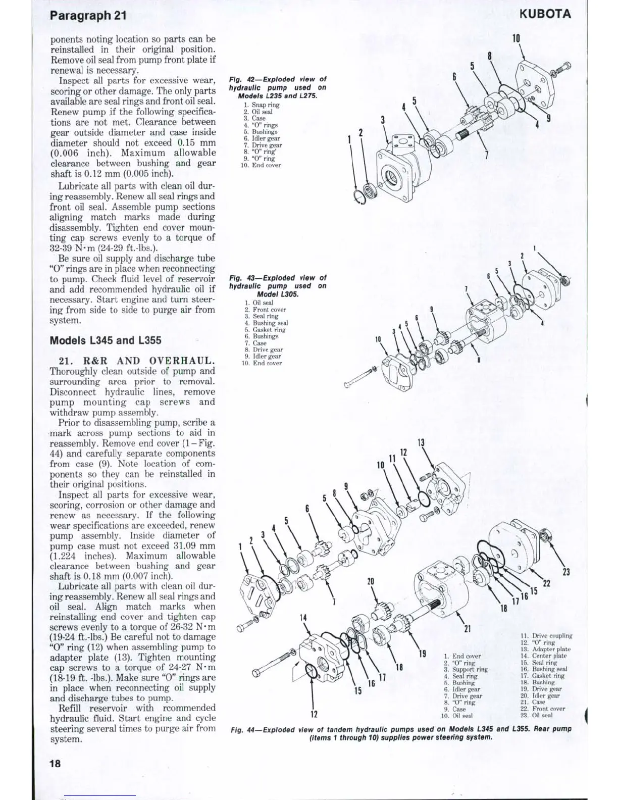
Prior to disassembling pump, scribe a
mark across pump sections to aid in
reassembly. Remove end cover (1-Fig.
44) and carefully separate components
from case (9). Note location of com-
ponents so they can be reinstalled in
their original positions.
Inspect all parts for excessive wear,
scoring, corrosion or other damage and
renew as necessary. If the following
wear specifications are exceeded, renew
pump assembly. Inside diameter of
pump case must not exceed 31.09 mm
(1.224 inches). Maximum allowable
clearance between bushing and gear
shaft is 0.18 mm (0.007 inch).
Lubricate all parts with clean oil dur-
ing reassembly. Renew all seal rings and
oil seal. Align match marks when
reinstalling end cover and tighten cap
screws evenly to a torque of 26-32
N • m
(19-24 ft.-lbs.) Be careful not to damage
"0"
ring (12) when assembling pump to
adapter plate (13). Tighten mounting
cap screws to a torque of 24-27 N-m
(18-19 ft. -lbs.). Make sure "0" rings are
in place when reconnecting oil supply
and discharge tubes to pump.
Refill reservoir with rcommended
hydraulic fluid. Start engine and cycle
steering several times to purge air from
system.
Fig. 42—Expioded view of
hydraulic pump used on
Models 1235 and L275.
1.
Snap ring
2.
Oil seal
3.
Case
4.
"0" rings
5.
Bushings >
6. Idler gear
7.
Drive gear
8. "0" ring'
9. "O"ring
10.
End cover
Ftg. 43—Exploded vtew of
hydraulic pump used on
Model L305.
1.
Oil seal
2.
Front cover
3.
Seal ring
4.
Bushing seal
5.
Gasket ring
6. Bushings
7.
Case
8. Drive gear
9. Idler gear
10.
End cover
IS
15
16
1.
End cover
2.
"0" ring
3.
Support ring
4.
Seal ring
5.
Bushing
6. Idler gear
7.
Drive gear
8. "0" ring
9. Case
10.
Oil seal
11.
Drive coupling
12.
"0" ring
13.
Adapter plate
14.
Center plate
15.
Seal ring
16.
Bushing seal
17.
Gasket ring
18.
Bushing
19.
Drive gear
20.
Idler gear
21.
Case
22.
Front cover
23.
Oil seal
Fig. 44—Expioded vtew of tandem hydrauiic pumps used on Models L345 and L355. Rear pump
(Items 1 through 10) supplies power steering system.
18
 Loading...


