Paragraphs 117-118
KUBOTA
117.
SYSTEM P R E S S U RE .
Hydraulic system relief pressure should
be 13240-14690 kPa (1920-2130 psi) on
all models. To check relief pressure,
remove plug from test port in hydraulic
cylinder cover and install a pressure
gage as shown in Fig. 154. Disconnect
linkage feedback rod (1-Fig. 156) and
remove position control lever upper
stop.
With hydraulic fluid temperature
at approximately 40°C (100°F) and
engine operating at high idle speed,
move draft control lever (if equipped)
and position control lever to highest
positions and note pressure gage
reading when relief valve is actuated. If
pressure is not within specified limits,
remove plug (1-Fig. 155) from relief
valve assembly and add or remove shims
(3) to obtain desired pressure relief set-
ting. Reconnect and adjust linkage feed-
back rod as outlined in following
paragraph,
118.
LINKAGE ADJUSTMENT.
To adjust position control feedback rod,
start engine and move position control
lever to "LIFT" position. Shorten feed-
back rod (Fig. 156) until relief valve is
actuated, then lengthen rod one full turn
and tighten locknut. Operate position
control lever from full down position to
full up position to make sure relief valve
is not actuated.
To adjust draft control (if so
equipped), attach a weight of approx-
imately 10 kg (20 pounds) to hitch lower
links.
Place position control lever in
"LIl^'T" position and draft control lever
in "DOWN" position. Operate engine at
rated speed and use a test bar (Fig. 157)
to lift top link holder all the way for-
ward. Hitch should start to raise when
draft control lever is moved to
"1"
mark-
ing on lever guide. Adjust length of
draft control rod (3-Fig. 158), if
necessary, to obtain recommended draft
control operation.
Fig. 157—Use a test bar to
lift top link holder fully for-
ward when adjusting draft
control linkage.
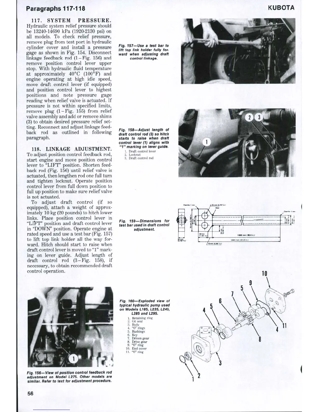
Fig. 15B—Adjust length of
draft controi rod (3) so hitch
starts to raise when draft
control lever (1) aligns with
"1"
marking on iever guide.
1.
Draft control lever
2.
Locknut
3.
Draft control rod
Fig. 159—Dimensions for
test bar used in draft controi
adjustment.
10
Fig. 160—Exploded view of
typical hydraulic pump used
on Models
L1B5,
L235,
L245,
1
z
:]
4
5
6
7
8
9
10
11
L2B5
and L295.
Retaining ring
Oil seal
Body
"0"
rings
Bushings
Key
Driven gear
Drive gear
"0"
ring
End cover
"0"
ring
11
Fig, 156—View of position control feedback rod
adjustment on Model L275. Other models are
simiiar.
Refer to text for adjustment procedure.
56
 Loading...


