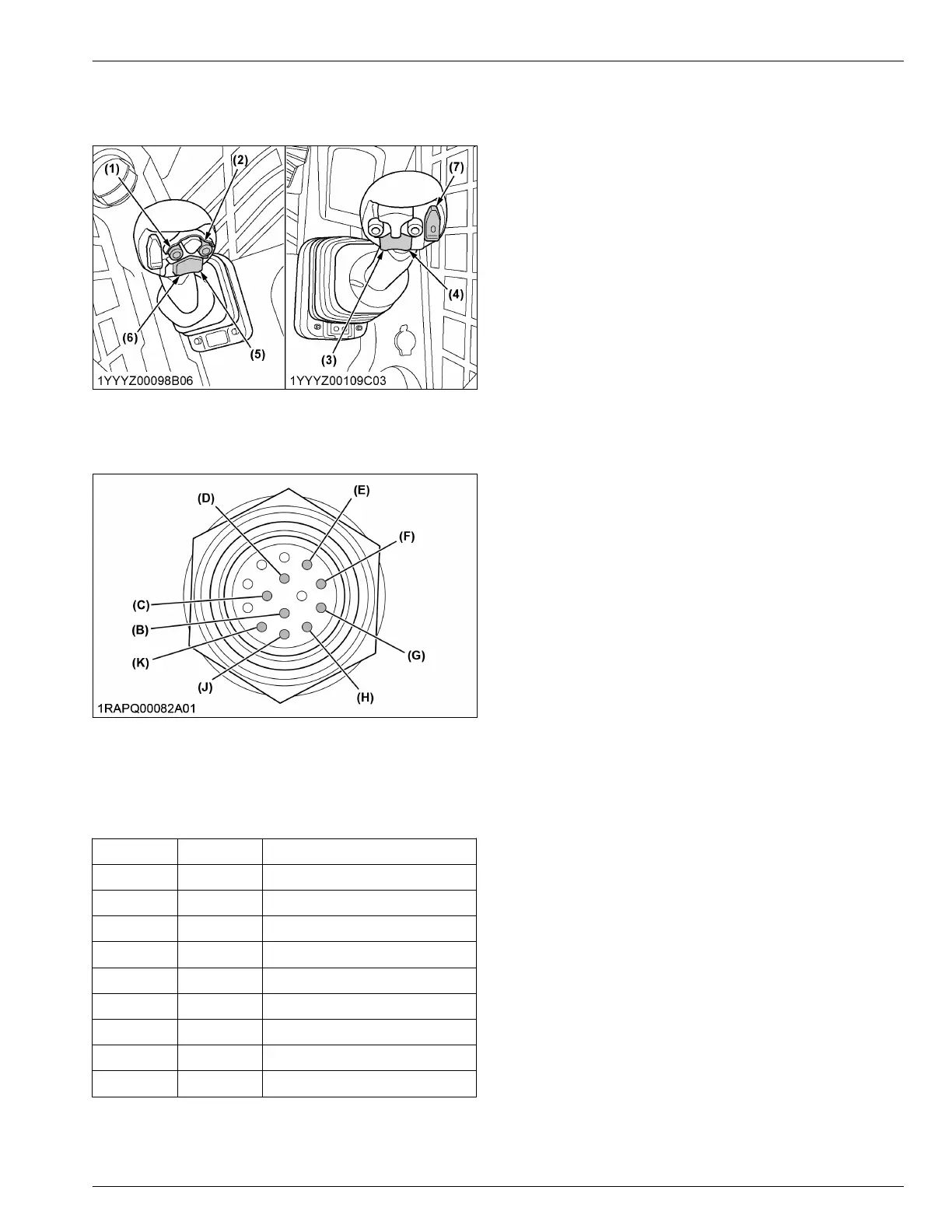
1. Press the numbered electrical control switch on the
left or right lever that corresponds with the desired
valve function, to be powered at +12 V.
(1) Ref. no. 1
(2) Ref. no. 2
(3) Ref. no. 3
(4) Ref. no. 4
(5) Ref. no. 5
(6) Ref. no. 6
(7) Ref. no. 7
(B) Pin port-B
(C) Pin port-C
(D) Pin port-D
(E) Pin port-E
(F) Pin port-F
(G) Pin port-G
(H) Pin port-H
(J) Pin port-J
(K) Pin port-K
14-pin coupler harness connection chart
Ref. no.
Pin port Remarks
- B GND
1 C AUX 1st func.
2 D AUX 1st func.
3 E AUX 2nd func.
4 F AUX 2nd func.
5 G AUX 3rd func.
6 H AUX 3rd func.
7 J AUX electrical mode change
- K +12 V
NOTE :
• AUX 3rd func. is momentary action.
• AUX electrical mode change is alternate
action.
HOW TO USE THE AUXILIARY HYDRAULIC CONTROL AUXILIARY HYDRAULIC
 Loading...