FS-9120DN/9520DN
2-2-1
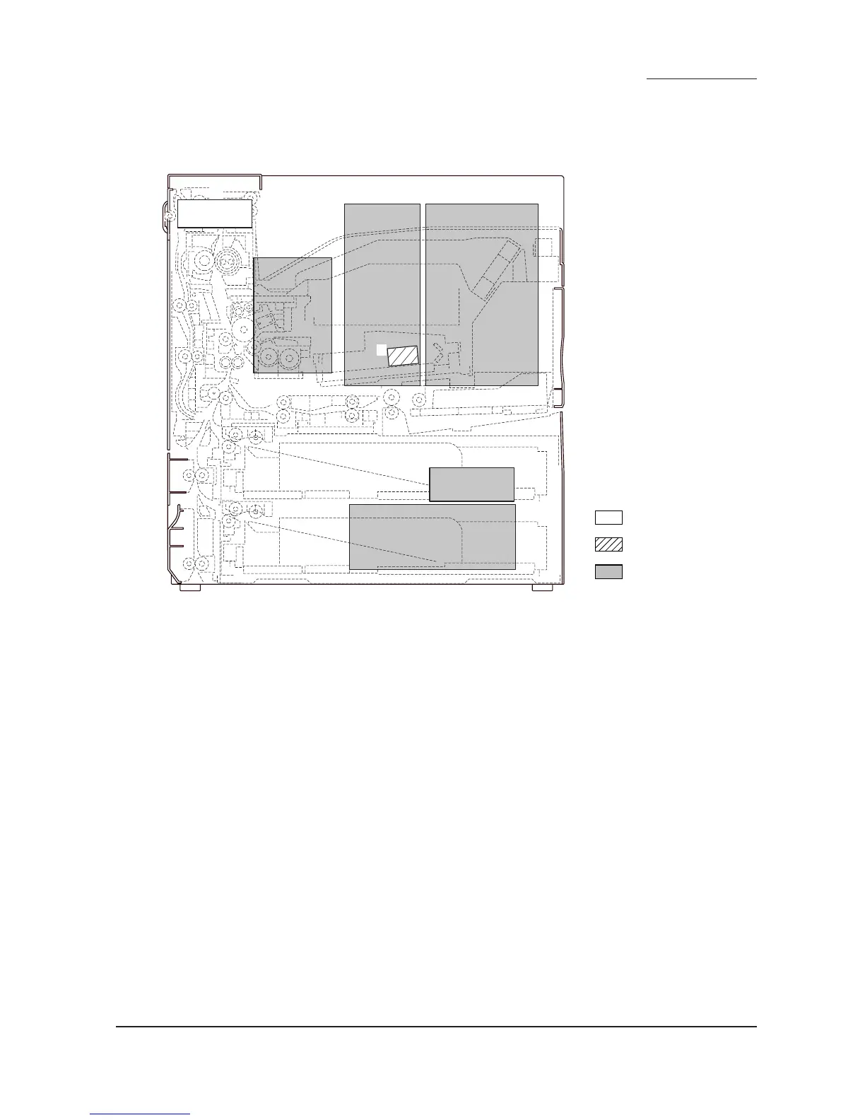
2-2-1 Electrical parts layout
(1) PWBs
Figure 2-2-1 PWBs
1. Main controller PWB (MPWB) ..................... Implements firmware for managing data processing for printing, interface
with PC and the network, etc.
2. Engine controller PWB (EPWB) ................... Controls printer hardware including electrical components.
3. Power supply unit (PSU) .............................. Generates +24 V DC, 12 V DC and 5 V DC; controls the fuser heater.
4. High-voltage transformer unit (HVTU) ......... Main charging. Generates developing bias and high voltages for
transfer.
5. Operator panel PWB (OPPWB) ................... Displays LCD messages and LED indicators. Controls key inputs.
6. Laser diode PWB (LDPWB) ......................... Generates and controls the laser beam.
7. Noise filter PWB (NFPWB) .......................... Reducts the noise.
3
7
5
2
1
4
Machine front
Machine inside
Machine rear
6
 Loading...