FS-9120DN/9520DN
2-3-1
2-3-1 Power supply unit
C201
C102
C101
D3
F1
F2
C5
+
++
+
Q1
T1
24 V DC
AC input
Power supply unit
Rectifier circuit
Fuser heater
control circuit
HEATER
MAIN ON
HEATER
SUB ON
GND
5 V DC
GND
HEATER
REM1
HEATER
REM2
ZERO CROSS
OUT
24 V DC
output
circuit
5 V DC
output
circuit
Switching
control circuit
IC1
D101
D102
Zero-cross
circuit
PC3
Overvoltage
detection circuit
IC201
PC1
PC2
TRA1
TRA2
PC5
PC4
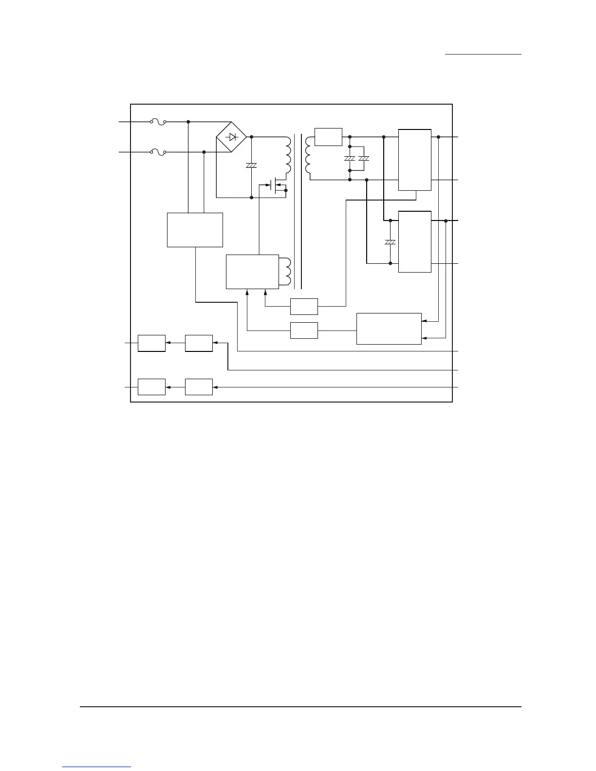
Figure 2-3-1 Power supply unit block diagram
The power supply unit (PSU) is a switching regulator that converts an AC input to generate 24 V DC and 5 V DC. It includes
a rectifier circuit, a switching regulator circuit, a 24 V DC output circuit, a 5 V DC output circuit and a fuser heater control
circuit.
The rectifier circuit full-wave rectifies the AC input using the diode bridge D3. The smoothing capacitor C5 smooths out the
pulsed current from the diode bridge.
In the switching control circuit, PWM controller IC1 turns the power MOSFET Q1 on and off to switch the current induced in
the primary coil of the transformer T1.
The 24 V DC output circuit smooths the current induced in the secondary coil of the transformer T1 via diodes D101 and
D102 and smoothing capacitors C101 and C102, and the output is controlled by the overvoltage detection circuit IC201 and
the power MOSFET Q201. For 24 V DC output, the PWM controller IC (IC1) of the switching control circuit changes the duty
of the switching pulse width of the power MOSFET Q1 via a photo coupler PC4 based on the output voltage status to adjust
the 24 V DC output.
The 5 V DC output circuit smooths the current induced in the secondary coil of the transformer T1 via diodes D101 and D102
and smoothing capacitors C101 and C102, and the output is controlled by the overvoltage detection circuit IC201 and the
power MOSFET Q201. For 5 V DC output, the PWM controller IC (IC1) of the switching control circuit changes the duty of
the switching pulse width of the power MOSFET Q1 via a photo coupler PC5 based on the output voltage status to adjust the
5 V DC output.
The overvoltage detection circuit IC201 monitors the overvoltage status of 24 V DC and 5 V DC, and when it detects an
abnormal status, it gives immediately feedback to the PWM controller IC (IC1) via a photocoupler PC5 to stop control
operation and moves the power source to a standby condition.
The fuser heater control circuit sends a waveform of which zero-cross is detected to the engine controller PWB (EPWB),
which controls the timing of HEATER REM 1 and 2 based on it to turn on the phototriacs PC1 and PC2. When the
phototriacs PC1 and PC2 turn on, AC current flows through the triacs TRA1 and TRA2 to turn the fuser heaters M and S on.
 Loading...