Page 10
TSC-3 Two-Speed Control
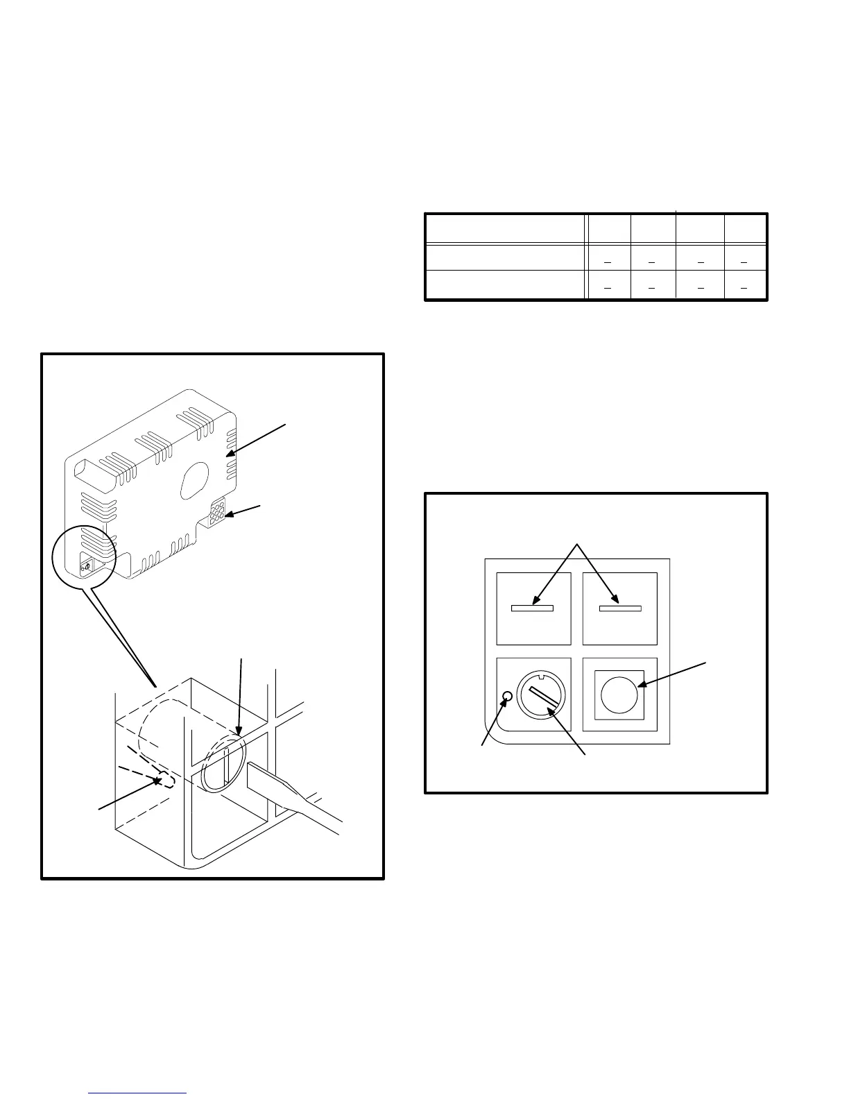
All early model HP21 -2 series units (single and three
phase) are equipped with a TSC-3 two-speed control. The
speed-control thermostat (formerly key number S55) has
been removed from the unit and incorporated into the cir-
cuitry of the TSC-3 control (see figure 6). The function and
operating sequence are otherwise identical to the TSC-2
plus the separate thermostat used in previous HP21 units.
The purpose of the speed control thermostat is to force the
compressor to operate on high speed when outdoor tem-
perature is low. It initiates a speed change delay and
automatically energizes high speed when temperature
drops below the setpoint. The setpoint is factory preset and
can be field adjusted.
FIGURE 6
TSC-3 TWO-SPEED CONTROL
(with built in speed control thermostat)
J44
SCREWDRIVER
TSC
TWO-SPEED CONTROL
SENSOR
TEMPERATURE
ADJUSTMENT
(potentiometer)
When temperature rises above the setpoint, the control
initiates a speed change delay and automatically ener-
gizes low speed.
The setpoint can be changed by adjusting the poten-
tiometer shown in figure 6. The potentiometer is factory
set as shown in table 5.
TABLE 5
Speed Control Thermostat
Adjustable Range
Cut-In
(Close on Temperature Drop)
Min.
Factory
Setting
Max
.
Cut-Out
(Open on Temperature Rise)
37+2°F 42+2°F 55+2°F
47+2°F 52+2°F 65+2°F
Mid.
46+2°F
56+2°F
To adjust the speed control thermostat, insert a small
slot screwdriver into the potentiometer as shown in fig-
ures 6 and 7. To lower the setpoint, turn the
potentiometer counter-clockwise. To raise the setpoint,
turn the potentiometer clockwise. Do not force the po-
tentiometer to turn past its stops; the potentiometer will
be damaged.
FIGURE 7
TSC-3 TWO-SPEED CONTROL
WINDING TEMPERATURE
SENSOR TERMINALS
TEMPERATURE
SENSOR
TEMPERATURE ADJUSTMENT
(shown in factory position)
OVERRIDE
BUTTON
(5 minute delay)
The unit wiring diagrams have been revised to reflect the
changes for the HP21-2 (TSC-3), and are shown in section
VII−Wiring Diagrams and Operation Sequence.
 Loading...
