Page 22
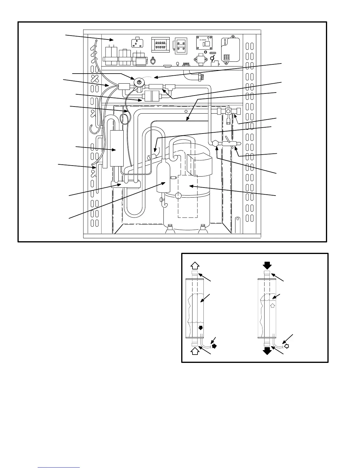
HP21 PLUMBING COMPONENTS
CHARGE COMPENSATOR
CHARGE
COMPENSATOR
LIQUID LINE
FIGURE 19
ACCUMULATOR
(BEHIND
COMPRESSOR)
LIQUID LINE
SERVICE VALVE
VAPOR LINE
SERVICE VALVE
DISCHARGE MUFFLER
*EXPANSION VALVE
EXPANSION VALVE
SENSING BULB
*FILTER/DRIER WITH
INTERNAL CHECK VALVE
THERMOMETER WELL
(−411, −511,−651 ONLY)
CONTROL BOX
(HP21 -1 shown)
STRAINER
EXPANSION VALVE
EQUALIZER LINE
REVERSING VALVE
DISTRIBUTOR
VAPOR
MANIFOLD
EXPANSION VALVE
SENSOR
CAP-TUBE
*HP21−6 AND LATE MODEL
UNITS WILL HAVE A BIFLOW
FILTER/DRIER AND EXPAN-
SION VALVE WITH INTER-
NAL CHECK VALVE
J−Charge Compensator
HP21−410, −650, −36 and −60 series units are equipped with
a charge compensator located in the vapor line between
the reversing valve and outdoor coil manifold. Figure 19
shows the relative location of the charge compensator in
the unit. The compensator is used to collect and store ex-
cess refrigerant in the heating mode. Figure 20 shows
operation of the charge compensator.
The charging procedure for these units is unchanged. Fol-
low the charging procedure outlined in the installation
instructions or in the Unit Information Manual.
In heating mode, the vapor line passing through the charge
compensator tank is cooler than the liquid line. Excess re-
frigerant (condensed liquid) from the indoor coil is trapped
by the compensator. The vapor is cooler than the liquid line
so liquid migrates from the liquid line to the compensator
tank where it is stored. In cooling mode, the vapor line
passing through the charge compensator tank is hotter
than the liquid line. Stored liquid is boiled and forced back
into the liquid line for circulation.
FIGURE 20
CHARGE COMPENSATOR OPERATION
During cooling mode, the va-
por line is hotter than the liq-
uid line. Stored liquid is
heated (boiled) and forced
back into circulation.
During heating mode, the va-
por line is cooler than the liq-
uid line. Excess refrigerant is
forced into the charge com-
pensator where it condenses
and collects.
Vapor Line
(To Outdoor Coil)
Vapor Line
(From Compressor Discharge Port)
Vapor Line
(From Outdoor Coil)
Vapor Line
(To Compressor Suction Port)
Stored Liquid
To Liquid Line
To be Circulated
Through Indoor Coil
Excess Refrigerant
To be Condensed and Stored
as Liquid
Compensator Tank
Compensator Tank
COOLING MODE
HEATING MODE
 Loading...
