Page 18
TABLE 12
CMC1 DEFROST INITIATION
NOTE−The symbol ∆T (pronounced delta T) is used to represent
the difference between liquid line temperature and ambient tem-
perature. The defrost control compares actual ∆T to a calculated
∆T to determine when to initiate defrost.
∆T = 0.30(Ambient Temp. − 15.0) + 1
The defrost control calculates ∆T by inserting the measured am-
bient temperature into the following equation. You can use the
equation to calculate the ∆T for any ambient temperature.
Once the defrost control has calculated ∆T, it compares the cal-
culated value to the actual measured ∆T. When the actual ∆T ex-
ceeds the calculated ∆T, defrost is initiated.
Actual Ambient
Temperature (°F)
Calculated ∆T
Control will initiate defrost when measured
∆T exceeds this value
35
30
25
20
15
10
0
7
5.5
4
2.5
1
0
0
As long as the liquid line remains above 65°F, the defrost
control remains turned off. If, during cooling operation, the
liquid line drops below 65°F, the defrost control will initiate
timing sequences, monitor liquid line and ambient temper-
atures and initiate a forced defrost after six hours of
compressor run time. If defrost is initiated while the unit is in
cooling mode, the outdoor fan will de-energize and the in-
door auxiliary heat will energize. A defrost initiated while
the unit is in cooling mode is an indicator that the unit may
be operating in low ambient conditions or further trouble-
shooting is required.
Defrost Control Components
1− Defrost LED
An LED on the circuit board lights to indicate the control
is in defrost mode.
2− Ambient Temperature Sensor
Ambient sensor (red cable) is permanently attached to
the circuit board. The sensing element is attached in-
side the ambient air port located in lower right corner of
compressor compartment (see figure 1).
3− Liquid Line Temperature Sensor
The blue cable is also permanently attached to the cir-
cuit board. The sensing element is attached to the
liquid line next to the expansion valve.
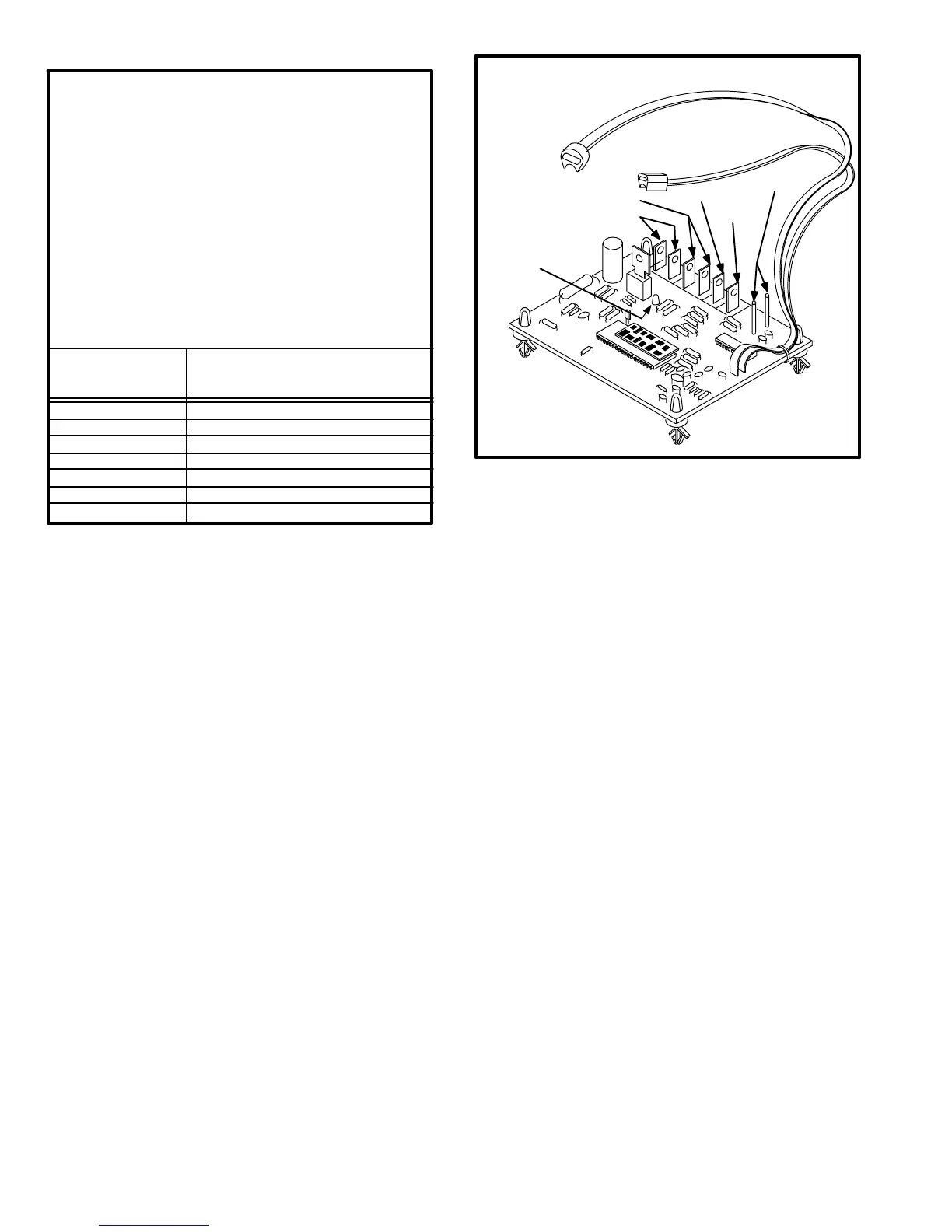
FIGURE 13
SOLID STATE DEFROST CONTROL
AMBIENT TEMP.
SENSOR (RED)
LIQUID LINE
TEMP. SENSOR
(BLUE)
LED (INDICATES
DEFROST MODE)
24VAC INPUT
24VAC COMMON
DEF RLY"
HOLD"
TEST"
4− 24V Terminal
Terminal 24V" receives 24VAC from the control trans-
former in the indoor unit (transformer T1 in CB21 series
units). This terminal powers the control’s internal timer,
relays and temperature probes. Terminal 24V" is pow-
ered anytime the indoor transformer is powered.
5− DEF RLY" Terminal
Terminal DEF RLY" controls defrost when connected
in series with defrost relay coil. An internal relay con-
nected to terminal DEF RLY" closes to allow external
defrost relay (K4) to energize and initiate defrost. At the
end of defrost period, internal relay connected to termi-
nal DEF RLY" opens to de−energize external defrost
relay.
6− COM" Terminal
Terminal COM" provides 24VAC Common.
7− HLD" Terminal
Terminal HLD" holds the internal timers in place be-
tween thermostat demands and allows the unit to
continue timing upon resumption of thermostat de-
mand. Terminal HLD" is connected directly to 1st
stage thermostat demand.
 Loading...
