Page 3
FIGURE 1
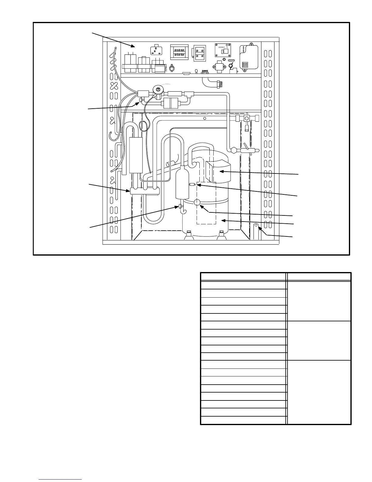
HP21 ELECTRICAL COMPONENTS
COMPRESSOR B1
HIGH PRESSURE
SWITCH S4
REVERSING VALVE
AND SOLENOID L1
COMPRESSOR
TERMINAL BOX
SERVICE LIGHT
THERMOSTAT S54
CRANKCASE
THERMOSTAT S40
UNIT CONTROL
AMBIENT AIR PORT
(DEFROST CONTROL
AMBIENT SENSOR)
DEFROST CONTROL
LIQUID LINE SENSOR
I−APPLICATION
All major components (indoor blower/coils) must be
matched according to Lennox recommendations for the
compressor to be covered under warranty. Refer to Engi-
neering Handbook for approved system matchups. A
misapplied system will cause erratic operation and can re-
sult in early failure of compressor or other components.
II−UNIT COMPONENTS
A−Control Transformer T19
All units are equipped with a line voltage to 24VAC trans-
former which supplies power to unit controls as shown in
table 1. Refer to unit wiring diagram for detailed information
regarding unit wiring.
B−Contactors K1 and K69
The compressor is energized by a set of contactors located
in the control box. Contactors in HP21 units are energized
as shown in table 2.
TABLE 1
HP21 Component Source of Power
24VAC from
Outdoor Unit
Transformer T19
Contactor K1
Contactor K69
Crankcase Thermostat S40
High Pressure Limit S4
24VAC from
Indoor Unit
Transformer T1
Two-Speed Control A14
Defrost Control CMC1
Defrost Relay K4
Speed Control Thermostat S55
Service Light Thermostat S54
Line Voltage
Potential Relay K31
Crankcase Heater HR1
Compressor Run Capacitor C5
Compressor Start Capacitor C7
Bleed Resistor R21
Fan Capacitor C1
Ambient Thermistor RT3
Compressor B1
Outdoor Fan B4
 Loading...
