Page 15
TABLE 8
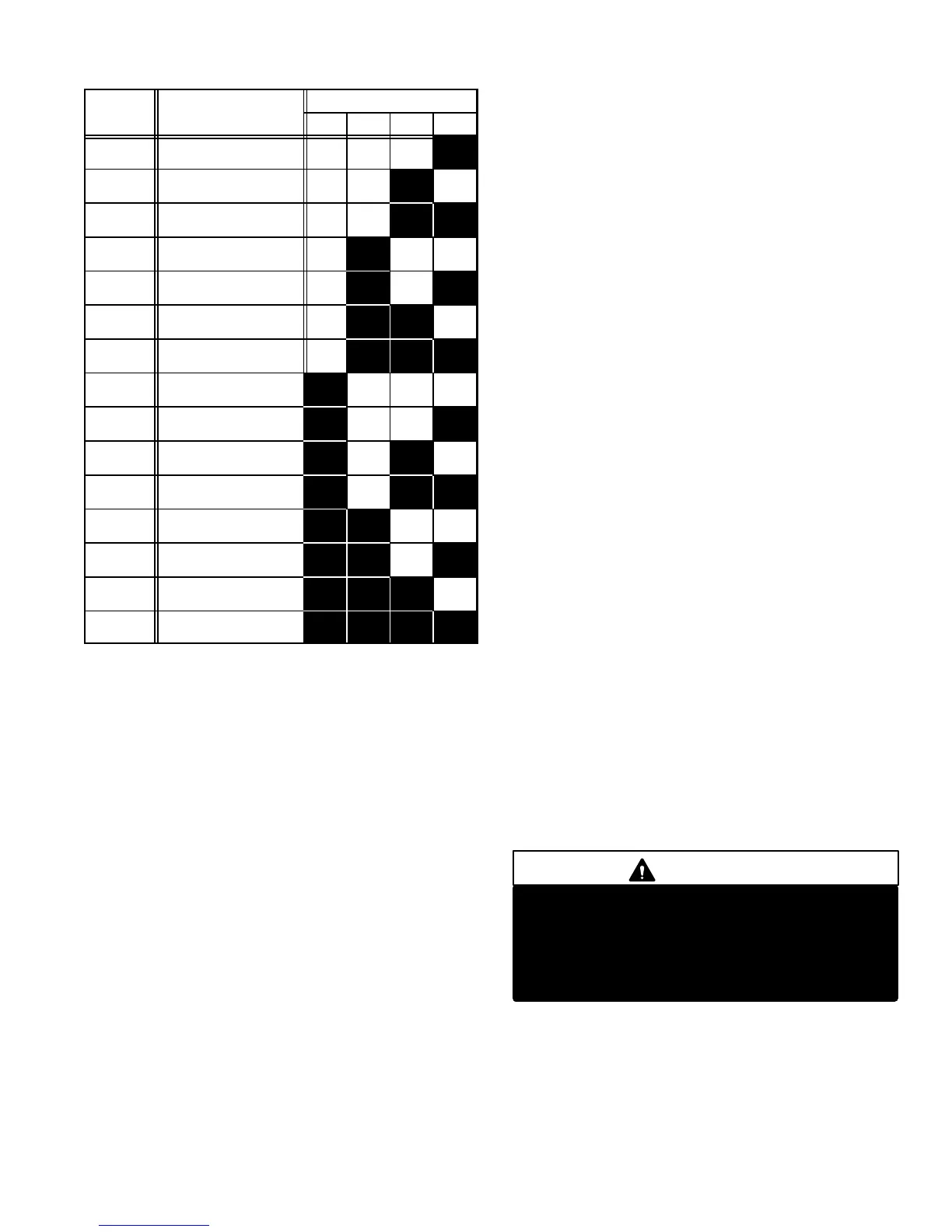
TSC-6 DIAGNOSTICS CODES
CODE
DISPLAY LIGHTS
NUMBER
CONDITION
8 4 2 1
1 Power loss for two
cycles
OFF OFF OFF ON
2 Input Indication OFF OFF ON OFF
3 Unsteady Input OFF OFF ON ON
4 Pressure Switch Open
<2 minutes
OFF ON OFF OFF
5 Pressure Switch Open
> 2 minutes
OFF ON OFF ON
6 Hot Compressor < 5
min. (or open sensor)
OFF ON ON OFF
7 Hot Compressor > 5 min.
(or open sensor)
OFF ON ON ON
8 Option 1 < 5 minutes ON OFF OFF OFF
9 Option 1 > 5 minutes ON OFF OFF ON
10 Option 2 Open ON OFF ON OFF
11 Compressor Temp.
Sensor Problem
ON OFF ON ON
12 Outdoor temperature
Sensor
ON ON OFF OFF
13 Not Used ON ON OFF
ON
14 Test Mode ON ON ON OFF
15 No Jumper in place
Indication
ON ON
ON
ON
Code 7 − Hot Compressor > Five Minutes
Code 7 indicates the compressor temperature exceeded
its limit after running more than five minutes. Code 7 is
stored.
Code 8 − Option 1 < Five Minutes
Code 8 occurs if the Option 1 safety device switch opens af-
ter the compressor runs less than five minutes. Code 8 is
stored.
Code 9 − Option 1 > Five Minutes
Code 9 occurs if the Option 1 safety device switch opens after
the compressor runs more than five minutes. Code 9 is
stored.
Code 10 − Option 2
Code 10 is displayed if the Option 2 safety device switch
opens. Code 10 is stored.
Code 11 − Compressor Temperature Sensor Shorted
This code indicates that the compressor temperature sensor
wires have shorted together. Code 11 is stored.
Code 12 − Outdoor Temperature Sensor
This code indicates a problem with the operation of the out-
door temperature sensor. Code 12 is stored.
Code 13 − Not Used
This code may be used in future models of the two−speed con-
trol, but at this time has no function and, therefore, is not
stored.
Code 14 − Test Mode
Code 14 does not indicate a problem. The control is in TEST
mode when this code is displayed. See Mode Jumper Selec-
tions section.
Code 15 − No Jumper in Place
Code 15 is displayed when the mode jumper is not in place.
Make sure jumper is placed securely across the selected set of
pins for the appropriate mode of operation.
SERVICE RELAY
The control has a built-in service relay. This relay controls the
thermostat service light or communicates with an alarm de-
vice. The relay signals the alarm device in such a manner that
the alarm device can distinguish between a lock out and a non-
lock out condition. The relay contacts are normally open when
no problems or lock out conditions occur. A non-lock out condi-
tion is reported by closing the contacts for the duration of the
next no-demand period. If the control goes into a lock out state,
the relay will close and remain closed until the next loss of de-
mand. If the service light on the room thermostat is connected
to the service relay, the light will turn on if the control is in a lock
out. It will not turn on if the control is detecting non-lock out
problems. In order for the service relay to indicate only a lock
out condition, one side of the relay must be wired to the alarm
and the other side to Y2. During a simultaneous Y1, Y2 de-
mand with a non-lock out condition, the alarm will energize for
a very short duration (.2 seconds). If both an alarm device and
thermostat service lights are used, an additional external relay
may be required depending on thermostat used.
OPTIONAL INPUTS
The control has two optional inputs for additional protection de-
vices. If options 1 or 2 are going to be used, move the three pin
mini-jumper to the YES side. OPT 1 input will lock out the com-
pressor on the third count. OPT 2 input will not lock out the
compressor at any time, but will display and store the problem
code (see Diagnostic code Table). These inputs are designed
for normally closed switches connected to 24VAC.
CAUTION
Do not remove the jumpers unless additional
protection controls are going to be installed. If OPT
1 jumper is not connected to the NO pin, the control
will lock out the compressor. If OPT 2 is not con-
nected to the NO pin, the display only shows the
problem code.
The unit wiring diagrams have been revised to reflect the
changes for the HP21-4/-5 (TSC-6), and are shown in section
VII−Wiring Diagrams and Operation Sequence.
 Loading...
