Page 29
B−Operation Sequence − Compressor
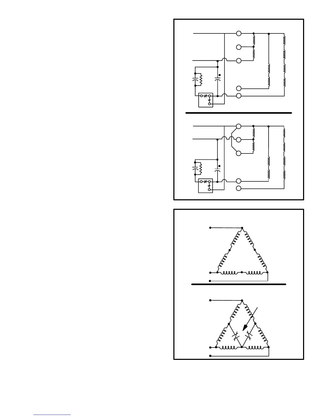
Single-Phase Compressor Startup
Figure 26 shows single-phase compressor windings. This
compressor has a two speed capacitor-start, capacitor-run
motor. For starting, the start and run capacitors are in par-
allel to provide the proper starting torque. The start
capacitor is disconnected by the start relay when the com-
pressor comes up to speed. The run capacitor remains
connected to the start winding and the motor runs as a two-
phase induction motor with improved power factor and
torque characteristics provided by the capacitor.
Low speed compressor operation is provided by powering
the run windings (internally connected in series) from ter-
minals 1 (common) and 7. The windings form a four-pole
motor operating at 1800 RPM. The four low speed start
windings are in series and are connected to terminals 1
(common) and 8. They are used with the start and run ca-
pacitors and start relay to start and bring the motor up to
speed.
High speed compressor operation is provided when the run
windings are connected in parallel; terminals 1 (common)
and 7 to L1 and terminal 2 to L2. The windings form a two-
pole motor operating at 3600 RPM. The two high speed
start windings are in series and connected to terminals 1
(common) and 3.
Three Phase Compressor Startup
Figure 27 shows the windings of three-phase two-speed
compressors. The compressors have two-speed, three-
phase induction motors. Capacitors are not needed to
provide the proper phase and torque characteristics.
Low speed operation is provided when the motor windings
are connected in a series Delta" circuit. The motor oper-
ates at 1800 RPM.
High speed operation is provided when the motor windings
are connected in a parallel Delta" circuit. Normally closed
contacts on the low speed contactor provide this connec-
tion.
FIGURE 26
MOTOR LEAD TERMINALS
LOW SPEED
START WINDINGS
HIGH SPEED
START WINDINGS
COMMON
RUN WINDINGS
RUN
CAP.
START
CAP.
START RELAY
8
3
7
2
1
MOTOR LEAD TERMINALS
COMMON
8
3
7
2
1
HIGH SPEED
START WINDINGS
RUN WINDINGS
LOW SPEED
START WINDINGS
START RELAY
START
CAP.
RUN
CAP.
SINGLE-PHASE MOTOR WINDINGS LOW SPEED
SINGLE-PHASE MOTOR WINDINGS HIGH SPEED
FIGURE 27
THREE-PHASE MOTOR WINDINGS LOW SPEED
SERIES DELTA" CIRCUIT
THREE-PHASE MOTOR WINDINGS HIGH SPEED
PARALLEL DELTA" CIRCUIT
L1
L2
L3
T1
T4
T3
T5
T2
T6
L1
L2
L3
T4
T3
T5T2T6
T1
COMPRESSOR
CONTACTOR K1−1
 Loading...
