Page 16
Q−Speed Control Thermostat S55
(Early Model HP21 −1 series units only)
The indoor thermostat regulates compressor speed when
the unit is operating in cooling mode. When the unit is oper-
ating in heating mode, speed control thermostat S55
regulates compressor speed.
1st stage heating demand from the indoor thermostat ener-
gizes the compressor (Y1 demand). Speed control
thermostat S55 controls compressor speed. Additional
heating demand from the indoor thermostat (W1 demand)
energizes the indoor auxiliary heat.
Speed control thermostat S55 (figure 10) is a SPST ther-
mostat located in the unit control box. The control uses a
cap-tube sensor to monitor the temperature inside the con-
trol box. The cap-tube sensor is coiled adjacent to the
control.
FIGURE 10
SPEED CONTROL THERMOSTAT S55
Temperature Sensor
(Cap-Tube)
S55 continually monitors the temperature inside the control
box. When control box temperature drops below the con-
trol setpoint, the control closes. When the control closes,
the contacts shunt across Y1 and Y2 inside the unit. When
heating demand is present and S55 is closed, the two-
speed control electrically sees a high speed demand. The
compressor operates at high speed until control box warms
and S55 opens.
TABLE 9
Speed Control Thermostat
Adjustable Range
Cut-In
(Close on Temperature Drop)
Min
.
Factory
Setting
Max
.
Cut-Out
(Open on Temperature Rise)
37+2°F 40+2°F 55+2°F
47+2°F 50+2°F 65+2°F
S55 has field adjustable setpoints. Temperature differential
(difference between cut-in and cut-out) is fixed and cannot
be adjusted. Table 9 shows S55 control setpoints.The con-
trol is factory set to close at 40+2°F on a temperature drop
and reset at 50+2°F on a temperature rise.
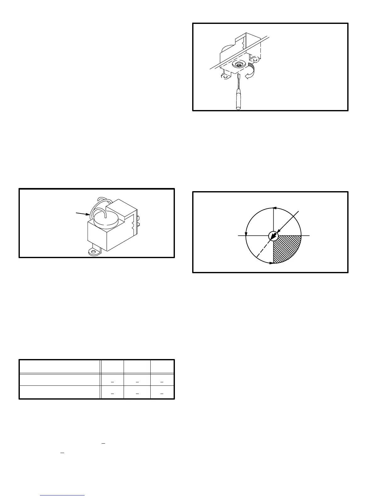
FIGURE 11
ADJUSTING SPEED CONTROL THERMOSTAT
Adjustment screw can be
accessed by inserting screw-
driver through slot in underside
of control box.
Turn screw clockwise to increase
switchover temperature.
Regional climatic conditions may require the control to be ad-
justed to a different setting. The adjustment screw is located
on the bottom of the control. A hole cut into the bottom shelf of
the control box provides access to the speed control from the
compressor compartment (see figure 11). Figure 12 shows
the adjustment range of the control. Turn adjustment screw
clockwise to raise the switchover temperature and counter-
clockwise to lower the switchover temperature.
FIGURE 12
SPEED CONTROL THERMOSTAT
ADJUSTMENT
SCREW
*HP21 FACTORY
SETTINGS
*40
37
55
49
43
R−Reversing Valve and Solenoid L1
A refrigerant reversing valve with electromechanical sole-
noid is used to reverse refrigerant flow during unit
operation. The reversing valve is energized during cooling
demand and during defrost.
S−Ambient Compensation Thermistor RT3
HP21 units are equipped with an ambient compensation
thermistor (RT3) attached to the outdoor fan motor bracket.
The thermistor is connected in series with the heat anticipa-
tion resistor inside the indoor thermostat. The thermistor
helps to prevent abnormal droop caused by the anticipation
resistors. RT3 is a NTC thermistor (negative temperature
coefficient; increase in temperature equals decrease in re-
sistance). As outdoor temperature increases, the
resistance through RT3 drops. As the resistance across
RT3 drops, the current through the heat anticipation resis-
tor increases. Therefore, heat anticipation increases as
outdoor temperature decreases. RT3 resistance values
are shown in table 10.
 Loading...
