Page 20
III−REFRIGERANT SYSTEM
A−Field Piping
Field refrigerant piping consists of liquid and vapor lines
from the outdoor unit (sweat connections). Use Lennox
L10 series line sets as shown in table 13 or field fabricated
refrigerant lines. Refer to the piping section of the Lennox
Service Unit Information Manual (SUI−803−L9) for proper
size, type and application of field−fabricated lines.
MODEL NO.
LIQUID VAPOR L10
LINE LINE LINE SETS
HP21−410
HP21−36
3/8 in. 3/4 in.
L10−41
20 ft. − 50 ft.
HP21−510
HP21−48
3/8 in. 7/8 in.
L10−65
30 ft. − 50 ft.
HP21−650
HP21−60
3/8 in. 1−1/8 in.
FIELD
FABRICATED
TABLE 13
B−Unit Circuitry
Conventional heat pump circuitry is used. A check valve
and expansion valve are used in parallel in the liquid line.
The check valve is closed when the unit is in heating mode
to force refrigerant through the expansion valve. The check
valve is open when the unit is in cooling mode and refriger-
ant is forced through the drier. Separate discharge and
suction service ports are provided at the compressor for
connection of gauge manifold during charging procedure.
Figures 16 and 18 show HP21 gauge connections.
C−Reversing Valve
HP21 units are equipped with a reversing valve which is
used to reverse refrigerant flow. The valve is de-energized
during heating mode to direct discharge gas to the indoor
coil. The valve is energized during cooling mode and dur-
ing defrost to direct discharge gas to the outdoor coil. A 24
volt solenoid is used to energize the reversing valve during
cooling and defrost demand.
D−Strainer
All units are equipped with a liquid line strainer located ad-
jacent to the expansion valve. The strainer is used to
protect the expansion valve from particulate matter enter-
ing the system (such as during charging).
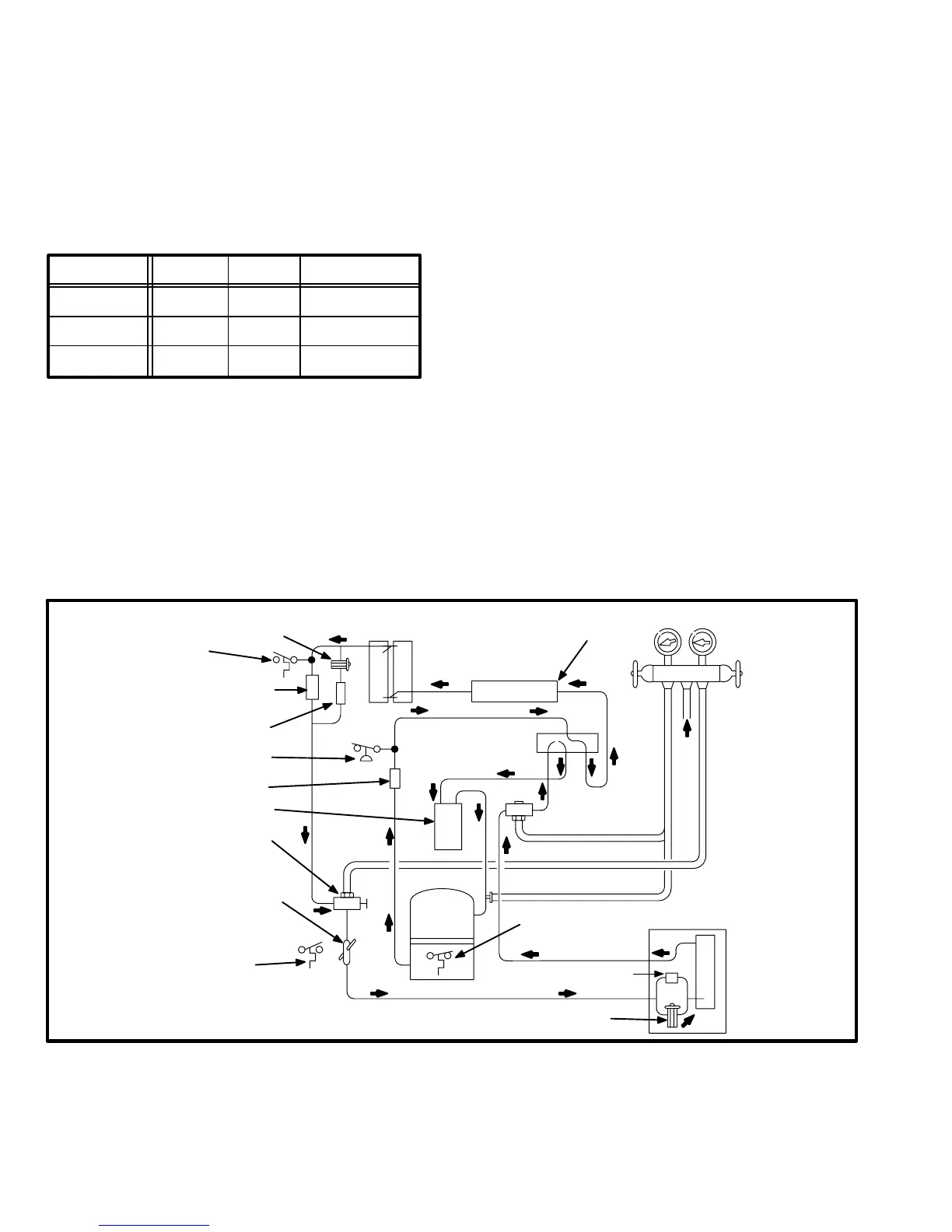
COOLING CYCLE CIRCUITRY
NOTE − Bold arrows indicate direction of
refrigerant flow in cooling mode.
THERMOMETER
WELL
REVERSING
VALV E
GAUGE MANIFOLD
INDOOR UNIT
VAPOR LINE
VALV E
VALV E
LIQUID LINE
EXPANSION
VALV E
COMPRESSOR
HIGH
PRESSURE
SWITCH
STRAIN-
ER
FILTER/DRIER
WITH INTERNAL
CHECK VALVE
OUTDOOR
COIL
DEFROST CONTROL
SENSOR
DEFROST CONTROL
AMBIENT SENSOR
CHARGE
COMPENSATOR
CHECK
VALV E
EXPANSION
VALV E
CRANKCASE
THERMOSTAT
ACCUMULATOR
MUFFLER
FIGURE 16
 Loading...
