Do you have a question about the Lennox HP21 and is the answer not in the manual?
Presents detailed electrical specifications for various HP21 models.
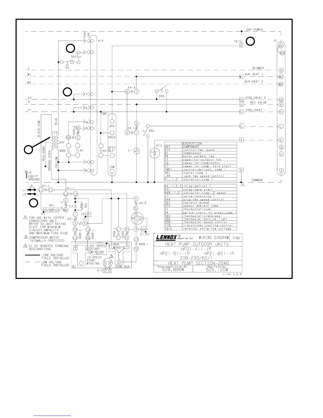
Details the function of the control transformer in supplying 24VAC to unit controls.
Explains the role of contactors K1 and K69 in energizing the compressor.
Describes the defrost relay's function in controlling defrost cycles.
Explains the hard start relay's role in the compressor starting circuit.
Details the low voltage terminal strip for thermostat wiring connections.
Refers to compressor specifications and terminal box details.
Provides specifications for outdoor fans used in HP21 units.
Describes the high pressure limit switch that interrupts unit operation.
Explains the crankcase thermostat's role in monitoring compressor temperature.
Details the service light thermostat mounted on the compressor discharge line.
Explains the start capacitor's function in single-phase compressor startup.
Describes the bleed resistor's purpose in discharging the start capacitor.
Details the run capacitor's role in maximizing motor efficiency.
Explains the fan capacitor's requirement for single-phase PSC outdoor fan motors.
Describes the dual capacitor used in late model single-phase units for motor efficiency.
Introduces two-speed controls, ESD precautions, and TSC-2.
Details liquid and vapor line requirements for field refrigerant piping.
Describes the conventional heat pump circuitry with check and expansion valves.
Explains the function of the reversing valve in directing refrigerant flow.
Details the liquid line strainer's role in protecting the expansion valve.
Details the filter/drier's location and function in the system.
Explains the externally equalized thermal expansion valve used as the primary device.
Locates the discharge muffler between the compressor and reversing valve.
Explains the suction line accumulator's location and purpose.
Describes the thermometer well for measuring liquid line temperature.
Outlines procedures for charging the system with refrigerant.
Details cleaning and inspection of the outdoor coil and fan.
Covers cleaning and inspection of indoor coils and lines.
Explains cleaning filters, inspecting coils, and checking blower.
Details components and procedures for ensuring control box watertightness.
Covers field wiring requirements and connection diagrams.
Explains compressor startup sequences for single and three-phase motors.
Details the step-by-step starting sequence for single-phase compressors.
Describes single-phase compressor startup for low and high speed operation.
Outlines the sequence of operations during single-phase cooling mode.
Outlines the sequence of operations during single-phase heating mode.
Details the defrost sequence for single-phase units.
Explains the starting sequence for three-phase compressors.
Describes three-phase compressor startup for low and high speed.
Outlines the sequence of operations during three-phase cooling mode.
Outlines the sequence of operations during three-phase heating mode.
Details the defrost sequence for three-phase units.
Details the cooling sequence for single-phase units with TSC control.
Details the heating sequence for single-phase units with TSC control.
Explains the defrost sequence for single-phase units.
Details the cooling sequence for three-phase units with TSC control.
Details the heating sequence for three-phase units with TSC control.
Explains the defrost sequence for three-phase units.
Provides a flowchart to diagnose problems with the TSC control.
Presents a diagnostic procedure for HP21 unit controls.

