Page 21
E−Filter/Drier
All HP21 units are equipped with a filter/drier located in a
circuit parallel to the expansion valve. The filter/drier is
equipped with an internal check valve. In heating mode
when refrigerant flow is reversed, the check valve is forced
closed and refrigerant is routed through the expansion
valve. During cooling mode the check valve opens and re-
frigerant flows freely through the filter/drier. HP21−6 and
late model HP21 units will use a Biflow filter /drier.
F−Expansion Valve
All HP21 series units use an externally equalized thermal
expansion valve as the primary expansion device in the
outdoor unit. The expansion valve is factory set, non−ad-
justable and non−serviceable. HP21−6 and late model
HP21 units will use an expansion valve with internal check
valve to pair with the biflow filter drier.
G−Discharge Muffler
All units are equipped with a discharge muffler connected
between the compressor discharge port and the reversing
valve. The discharge muffler is located immediately in front
of the compressor in the compressor compartment. See
figure 19.
H−Accumulator
All units are equipped with a suction line accumulator con-
nected between the reversing valve and the compressor
suction port. The accumulator is located immediately be-
hind the compressor in the compressor compartment. See
figure 19.
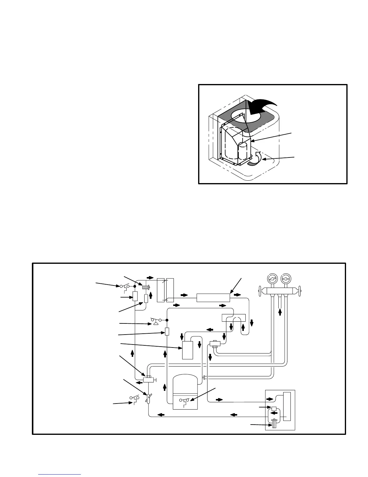
The accumulator can be accessed without removing the
compressor. To access the accumulator, remove the out-
door fan guard. Then remove the fan motor and bracket as
an assembly. By reaching inside the fan opening, remove
all screws securing the compressor wrapper to the unit
(see figure 17). Then hinge the wrapper up out of the way to
access the accumulator.
FIGURE 17
ACCESS TO ACCUMULATOR
REMOVE FAN GUARD AND
FAN. REACH THROUGH
OPENING.
REMOVE SCREWS
SECURING WRAPPER
TO UNIT.
HINGE WRAPPER
OUT OF WAY
I−Thermometer Well
Early model units only are equipped with a thermometer
well for use in measuring liquid line temperature when
charging the unit. The thermometer well is used in all Len-
nox recommended charging procedures. It is located in the
liquid line adjacent to the liquid line service valve.
HEATING CYCLE CIRCUITRY
NOTE − Bold arrows indicate direction of
refrigerant flow in cooling mode.
THERMOMETER
WELL
REVERSING
VALV E
GAUGE MANIFOLD
INDOOR UNIT
VAPOR LINE
VALV E
VALV E
LIQUID LINE
EXPANSION
VALV E
COMPRESSOR
HIGH
PRESSURE
SWITCH
STRAINER
FILTER/DRIER
WITH INTERNAL
CHECK VALVE
OUTDOOR
COIL
DEFROST CONTROL
SENSOR
DEFROST CONTROL
AMBIENT SENSOR
CHARGE
COMPENSATOR
CHECK
VALV E
EXPANSION
VALV E
CRANKCASE
THERMOSTAT
ACCUMULATOR
MUFFLER
FIGURE 18
 Loading...
