Page 23
K−Service Valves
The liquid line and vapor line service valves and gauge
ports are accessible on the inside of the unit by removing
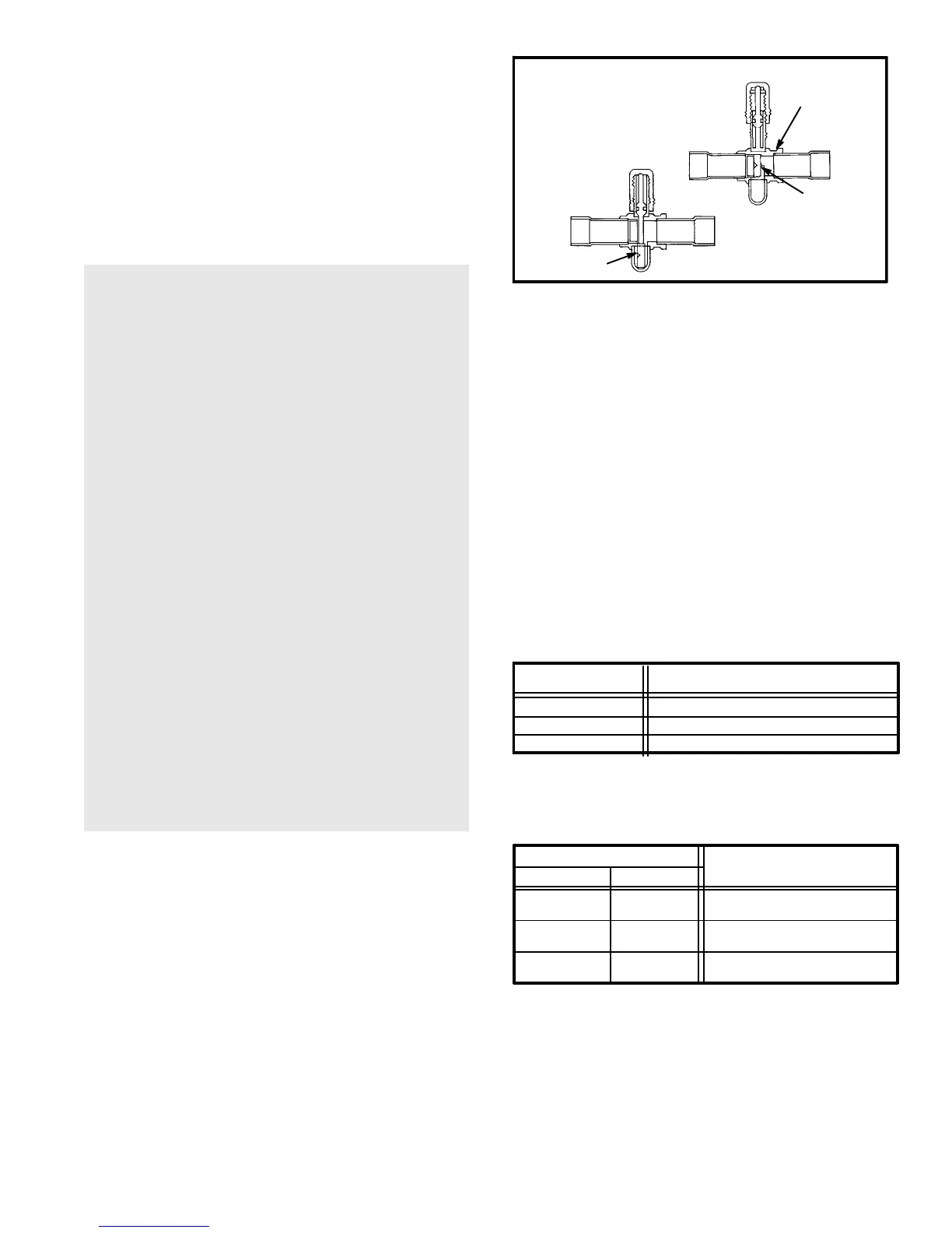
the compressor access panel. The one shot" vapor line
service valve (figure 21) cannot be closed once it has been
opened. Both service valves are equipped with gauge
ports which can be used for leak testing, evacuating, charg-
ing and checking charge. A separate gauge port is
provided for checking the suction pressure when the unit is
in the heating cycle.
CAUTION-When sweating any valve, always wrap a
wet rag around the valve and adjoining pipe. Cool
joint with wet rag after brazing.
WARNING-The liquid line valve is not a back-seat-
ing valve (has valve core in service port) and it
should not be opened more than 5 turns. Opening
or closing the valve does not close the service port.
To operate the valve, fully insert hex wrench into
the stem and BACK OUT COUNTER-CLOCKWISE
UNTIL THE STEM JUST TOUCHES THE RETAINING
RING.
If visual verification of the valve stem reaching the
retaining ring is impossible, STOP BACKING-OUT
THE VALVE STEM WHEN THE SLIGHTEST RE-
SISTANCE IS FELT.
Because of the small size and therefore the reduced
resistance, BACK-OUT THE LIQUID VALVE 5
TURNS MAXIMUM to prevent going past the retain-
ing ring.
If the valve stem is backed-out past the retaining
ring, the O-ring can be damaged causing leakage or
system pressure could force the valve stem out of
the valve body possibly causing personal injury. In
the event the retaining ring is missing, do not at-
tempt to open the valve.
VAPOR LINE VALVE
FRANGIBLE PLUG
FRANGIBLE PLUG
VALVE BODY
HP21 UNITS USE ONE−SHOT
VAPOR LINE VALVES. ONCE
OPENED, THEY CANNOT BE
CLOSED.
NEW UNIT
VALVE CLOSED
VALVE OPEN
FIGURE 21
After servicing unit, replace valve cap finger tight, then
tighten an additional 1/2 turn (1/2 hex flat). Cap must be re-
placed to prevent leaks.
L−Low Ambient Control Kit (Optional)
The HP21 unit will operate satisfactorily down to 45°F (7°C)
outdoor air temperature without any additional controls. For
cases where operation of the unit is required at low ambients,
a Low Ambient Control Kit LB-57113BM (27J00) can be add-
ed in the field, enabling the unit to operate properly down to
30°F (-1°C). Included in the kit are the low ambient relay
(K58) and the low pressure switch (S11).
IV−CHARGING
The unit is factory−charged with the amount of R−22 refrig-
erant indicated on the unit rating plate. This charge, as
shown in figure 14, is based on a matching indoor coil and
outdoor coil with 15 feet of line set.
TABLE 14
Model Refrigerant Charge R−22
HP21−410, −36
HP21−510, −48
HP21−650, −60
13 lbs. 8 oz.
15 lbs. 8 oz.
19 lbs. 2 oz.
For varying lengths of line set, refer to table 15 for refriger-
ant charge adjustment. A blank space is provided on the
unit rating plate to list actual field charge.
LINE SET DIAMETER
Ounces per foot
adjust from 15 ft.
line set*
Vapor Liquid
1/2 ounce
3/4 ounce
3/4 ounce
3/8 in.
(10mm)
3/8 in.
(10mm)
3/8 in.
(10mm)
3/4 in.
(19mm)
7/8 in.
(22mm)
1−1/8 in.
(29mm)
TABLE 15
* If line length is greater than 15 feet, add this amount. If line length is
less than 15 feet, subtract this amount.
(15ml)
(21ml)
(21ml)
A−Leak Testing
1− Attach gauge manifold and connect a drum of dry nitro-
gen to center port of gauge manifold.
 Loading...
