Page 12
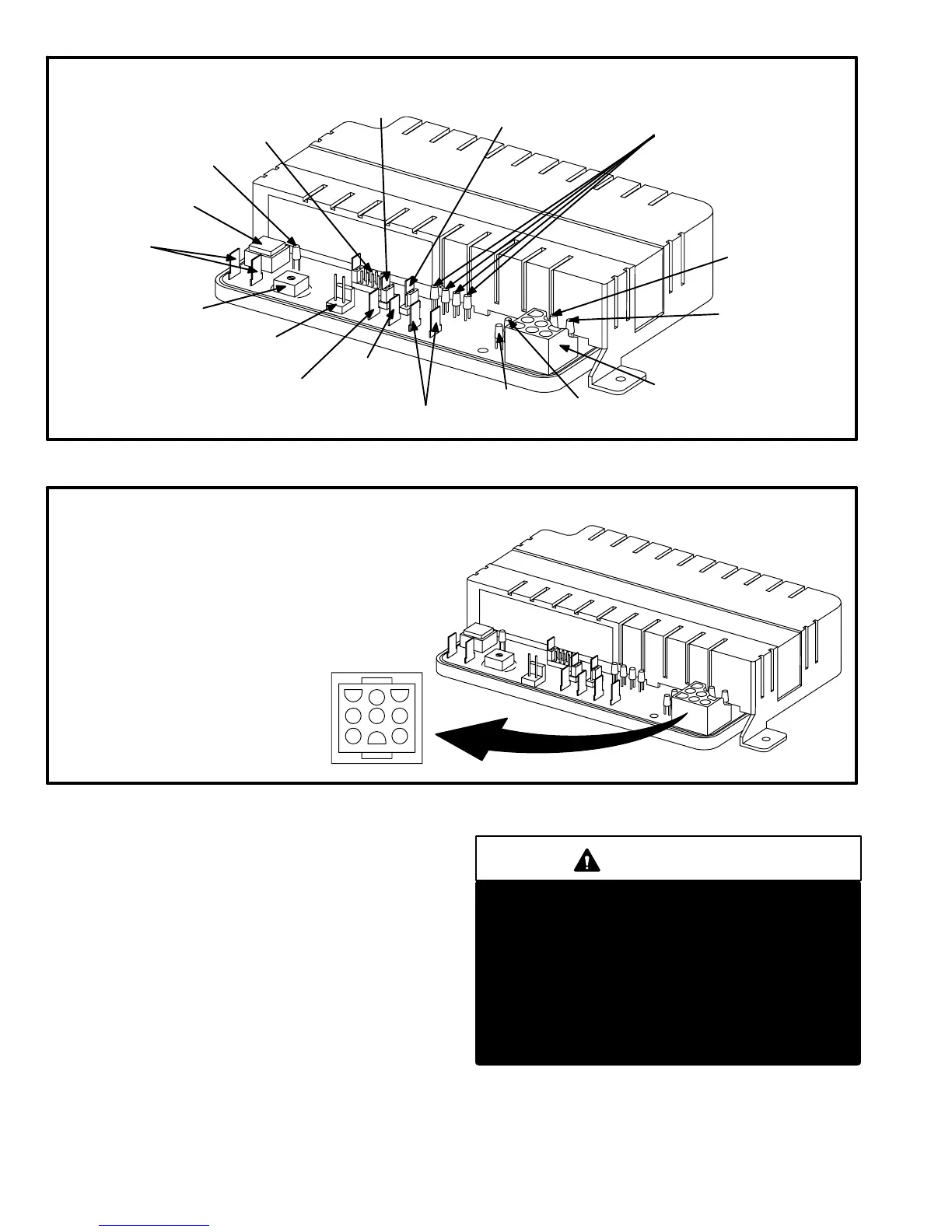
FIGURE 8
TSC-6 (A14) TWO-SPEED CONTROL COMPONENTS
DIAGNOSTIC LEDs
D8, D4, D2, D1
Y1 LED
Y2 LED
MAIN CONTROL
PLUG
HIGH SPEED
LED
LOW SPEED
LED
SERVICE RELAY
CONNECTORS
HEARTBEAT
LED
MODE
SELECTION
JUMPERS
OPTION 1 ENABLE
JUMPER
OPTION 2 ENABLE
JUMPER
OPTION 2
CONNECTOR
COMPRESSOR
SENSOR
CONNECTORS
MANUAL
OVERRIDE
BUTTON
OPTION 1
CONNECTOR
LOW SPEED lock out
TEMP. ADJUSTMENT
OUTDOOR
TEMP. SENSOR
CONNECTOR
FIGURE 9
TSC-6 (A14) MAIN CONTROL PLUG
1
2
3
456
789
JP44
JP44-1 24VAC POWER (INPUT)
JP44-2 24VAC COMMON
JP44-3 24VAC (SPARE, NOT USED)
JP44-4 2nd STAGE THERMOSTAT DEMAND
JP44-5 THERMOSTAT COMMON (C)
JP44-6 1st STAGE THERMOSTAT DEMAND
JP44-7 24VAC FROM SAFETY SWITCHES
TO INTERNAL CONTACTOR COIL (INPUT)
JP44-8 HIGH SPEED (24VAC OUTPUT)
JP44-9 LOW SPEED (24VAC OUTPUT)
Two-Speed Control Fault Conditions
If the control is in low speed operation, high speed operation,
OFF" mode or speed change delay, the control counts" or ac-
cumulates faults on an internal cycle counter. Only faults which
occur during compressor operation and which cause the com-
pressor to shut off are counted. After a fault is counted, the
control stops unit operation, resets and begins a five-minute
time delay (step 2, operation sequence). If the control senses a
fault at the end of five minutes, the unit will not restart. If the
control counts three faults during the same thermostat de-
mand, the control locks out unit operation.
IMPORTANT
If the cycle counter counts three faults during the
same thermostat demand, the control locks out. The
outdoor unit remains inoperable until thermostat de-
mand is broken. This indicates further troubleshoot-
ing is needed. Though the control can be reset by
breaking thermostat demand, the unit may remain in-
operable. The high pressure or low pressure condi-
tions may still exist and must be located and cor-
rected before the unit can be placed back in service.
See diagnostic codes to determine problem.
 Loading...
