Page 4
BACnet
R
t Listed
TB1−7 (M1) J2 (M2)
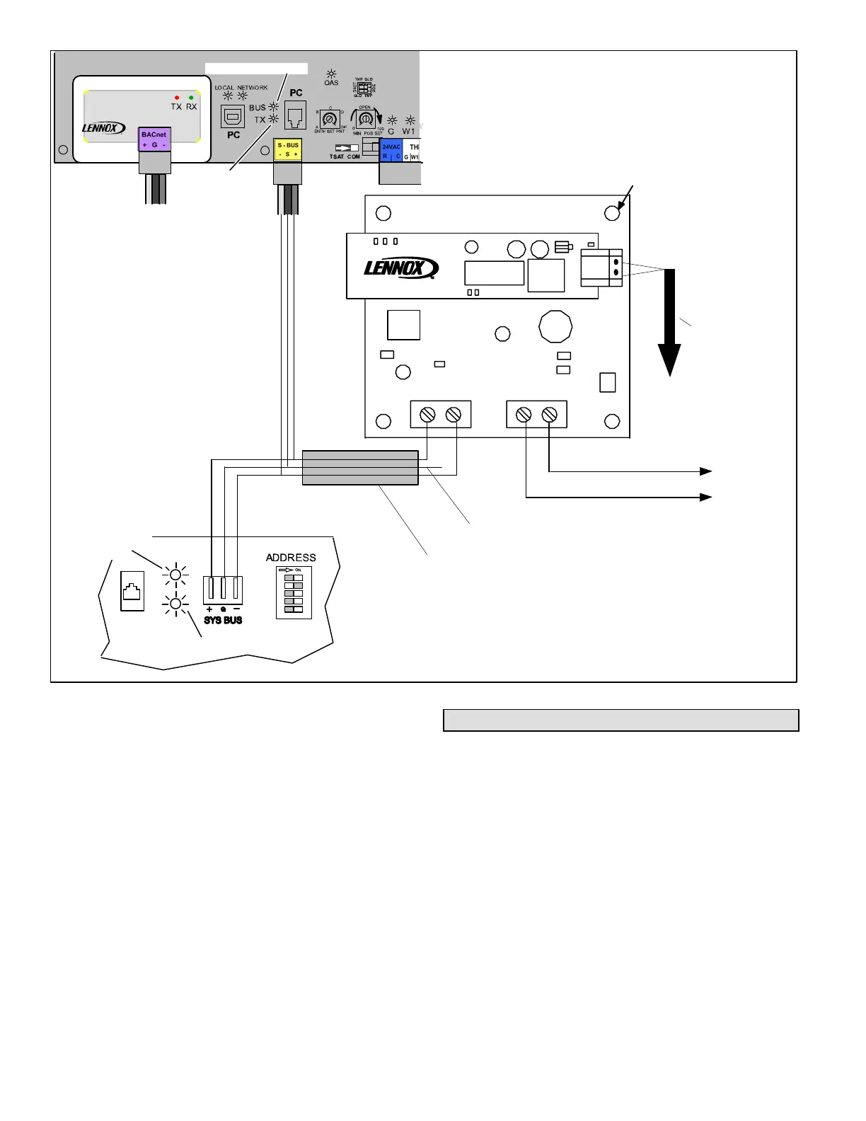
LONWORKS
NETWORK
COMMUNICATION
CABLE (TWISTED PAIR)
1/2" MOUNTING STANDOFF (4).
USE #6 SCREWS TO SECURE.
TB61
12 12
TB63
TB62
A147
SYSBUS
+−
24VAC
HOT COM
BELDEN 8471
OR EQUIVALENT
TWISTED PAIR
CABLE
M1−7. M1−8
Integrated
Modular
Controller
M2 UNIT
CONTROLLER
DETAIL A
TRANSMIT LED
TX
BUS
IMC
1
2
4
8
16
UNIT ADDRESS
DIP SWITCH
NETWORK LED
TRANSMIT
LED
M1−7, M1−8
IMC
DETAIL B
NETWORK
LED
SHIELD WIRE NOT
CONNECTED
M2 Unit
Controller
TB1−6 (M1) J18 (M2)
Figure 6. LonTALK Module Wiring
Zone Sensor Installation
The unit controller is factory set in local thermostat system
mode. In this mode the unit will respond to standard 24
VAC thermostat signals that are hardwired to the unit TB1
field wiring terminal block (M1) or SmartWiret connec-
tions (M2). For LonWorks network installations the unit
controller uses a local zone sensor or a remote LonTalk
thermostat zone sensor to operate the unit instead of a lo-
cal thermostat.
Install the sensor according to manufacturer’s instructions.
NOTE − Lennox zone sensor requires twisted pair shielded
cable.
NOTE − LonTalk zone sensor must be commissioned ac-
cording to manufacturer’s instructions.
Configuring the Unit Controller
Settings: M1 Controllers
Use the IMC pushbutton and DIP switches to manually ad-
just the following control parameters (see IMC manual). A
PC can also be used with Unit Controller software and a
PC converter.
Lennox Zone Sensor Installed:
1. Set ECTO 6.01 to option 3 (zone sensor system mode
with return air sensor back−up).
2. Set ECTO 6.17 to option 1 (continuous blower during
occupied).
3. Set ECTO 6.02−6.05 as specified (back−up occupied
and unoccupied heating and cooling setpoints).
 Loading...
