Page 3
506373−01 11/2011
Never test for gas leaks with an open flame. Check all
connections with a commercially available soap solution
made specifically for leak detection.
NOTE − Furnace must be adjusted to obtain a
temperature rise (high and low fire) within the range(s)
specified on the unit nameplate. Failure to do so may
cause erratic limit operation.
Canada
The unit is CSA International (CSA) certified for
combination heating/cooling for outdoor installations and
non−residential use only at the clearances to combustible
materials as listed on the unit nameplate.
Installation of CSA international certified units must
conform with current standard CSA B149.1, Natural Gas
and Propane Installation Codes" and applicable local
codes. Authorities having jurisdiction should be consulted
before installation.
The unit must be wired and electrically grounded
according to local codes or, in the absence of local codes,
current CSA Standard C22.1 Canadian Electrical Code
Part 1. Installation of combination heating/cooling units
must also conform with current CSA Standard B52
Mechanical Refrigeration Code."
Connect Gas Piping
A manual main shut−off valve must be installed external
to the unit when local codes require the installation of
such a valve.
Install a ground joint union between the gas control
manifold and the main manual shut−off valve.
When making piping connections a drip leg should be
installed on vertical pipe runs to serve as a trap for
sediment or condensate.
A 1/8" N.P.T. plugged tap is located on gas valve for test
gauge connection. See figure 4 or 5 for tap location. See
figure 6 for for gas supply piping entry through the side of
the unit and figure 7 for gas piping through the bottom of
the unit. A kit is required when routing gas supply piping
through the bottom of the unit.
Compounds used on threaded joints of gas piping must
be resistant to the actions of liquified petroleum gases.
GAS VALVE SHOWN IN ON POSITION
Honeywell VR8205 Gas Valve with ON/OFF Lever
Single−Stage
MANIFOLD
PRESSURE
OUTLET
INLET
PRESSURE
PORT
MANIFOLD
PRESSURE
ADJUSTMENT
SCREW
FIGURE 4
HONEYWELL VR8205Q/VR8305Q SERIES GAS VALVE
Gas valve knob is shown in OFF position.
FIGURE 5
LOW FIRE
ADJUSTMENT
HIGH FIRE
ADJUSTMENT
MANIFOLD
INLET
PRESSURE
TAP
MANIFOLD
OUTLET
PRESSURE
TAP
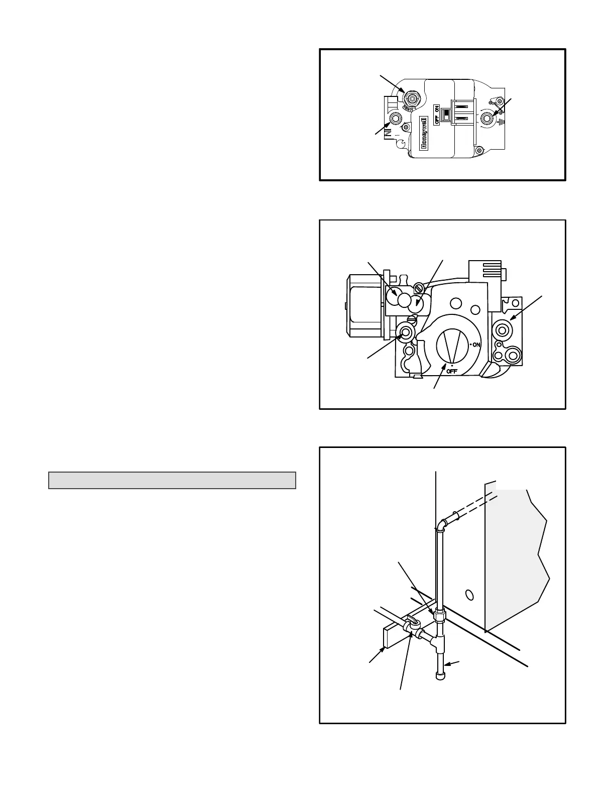
FIGURE 6
TO GAS
SUPPLY
MANUAL MAIN
SHUT−OFF VALVE
GAS PIPING
SUPPORT
GROUND
JOINT UNION
(REFER TO
LOCAL CODES)
DRIP LEG
OUTSIDE OF UNIT GAS PIPE CONNECTION
TO GAS
VALVE
 Loading...
