Page 12
LGH/LCH036, 048, 060, 072
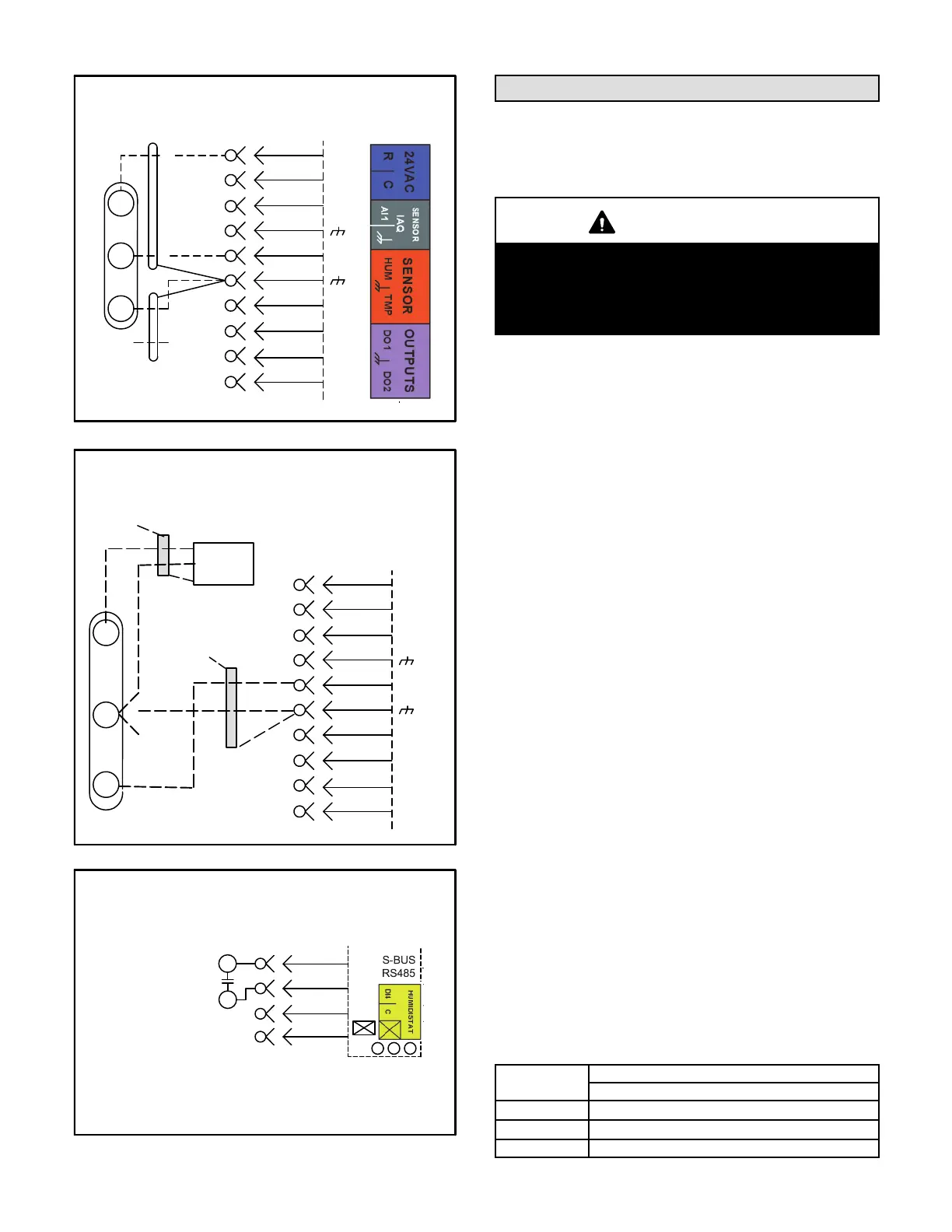
FIGURE 16
FIELD WIRING REHEAT UNITS (Using A Humidity
Sensor With Less Than 150 Ft. Wire Runs)
9
8
10
11
12
2
J262B
5
P298
J298A
6
1
2
B
3
4
C
5
6
7
D
10
A91
VIN
VO
GND
P262
R
C
AI−1
HUM
TMP
DO−1
C
DI−1
DO−2
FIGURE 17
FIELD WIRING REHEAT UNITS (Using A Humidity
Sensor With More than 150 Ft. Wire Runs)
ISOLATED 24V
TRANSFORMER
9
8
P298
J298A
1
2
B
3
4
C
5
6
7
D
10
A91
VIN
VO
GND
R
C
AI-1
HUM
TMP
DO-1
C
DI-1
DO-2
NOT
CONNECTED
NOT
CONNECTED
DRAIN
A55 UNIT
CONTROLLER
FIGURE 18
FIELD WIRING REHEAT UNITS
(Using A Dehumidification Switch)
7
10
8
9
R
DI−4
C
Use 24 VAC (R) from any terminal
available on J299−2, −5, or −7.
J299
DEHUMIDIFICATION
SWITCH
Blower Operation and Adjustments
Three-, four- and five-ton units are equipped with either
direct drive or multi-pole belt drive blowers. 6-ton units
are available with belt drive blowers only.
IMPORTANT
Three phase scroll compressors must be phased
sequentially for correct compressor and blower
rotation. Follow “COOLING START-UP” section of
installation instructions to ensure proper compres
sor and blower operation.
A-Blower Operation
Refer to the Unit Controller Installation and Setup Guide
to energize blower. Use the menu navigation arrows and
select button; see Service - Test.
B-Determining Unit CFM
1- The following measurements must be made with air
filters in place.
IMPORTANT - On units equipped with direct drive
blowers, determine and adjust high speed CFM before
low speed CFM. Low speed CFM should be adjusted to
2/3 of high speed CFM. A low speed adjustment less than
2/3 of high speed will improve humidity removal; refer to
product data for more information.
2- With all access panels in place, measure static
pressure external to unit (from supply to return).
Blower performance data is based on static pressure
readings taken in locations shown in figure 19.
Note - Static pressure readings can vary if not taken
where shown.
3- Measure the indoor blower wheel RPM.
4- Referring to Page 16 through Page 26, use static
pressure and RPM readings to determine unit CFM.
Use Page 27 when installing units with any of the
options or accessories listed. Refer to table 3 for
minimum airflow when electric heat is installed.
TABLE 3
MINIMUM AIRFLOW-LC UNITS WITH ELECTRIC HEAT
(BELT DRIVE)
Kw
CFM
Downflow & Horizontal Airflow
LCH036HE
1080
LCH048HE
1280
LCH060HE
1600
 Loading...
