Page 7
LGH036-360 User's
Servicing Filter
Units are equipped with filters as shown in table 1. Filters
should be checked monthly and replaced when
necessary. Take note of air flow direction marking on filter
frame when reinstalling filters. See figure 7.
NOTE - Replace factory-installed filters within 30 days of
initial unit start-up. Refer to local codes or appropriate
jurisdiction for approved filters.
WARNING
Units are shipped from the factory with temporary
filters. Replace filters before building is occupied.
Damage to unit could result if filters are not re
placed with approved filters. Refer to appropriate
codes.
TABLE 1
UNIT FILTERS
Unit Qty Filter Size - inches (mm)
036, 048 4 16 X 20 X 2 (406 X 508 X 51)
060, 072 4 20 X 20 X 2 (508 X 508 X 51)
092, 102, 120, 150 4 20 X 25 X 2 (457 X 610 X 51)
156 - 300S 6 24 X 24 X 2 (610 X 610 X 51)
242, 300H, 360 12 20 X 20 X 2 (508 X 508 X 51)
NOTE - Filters must be ULC approved or equivalent for
use in Canada.
REMOVE FILTERS
FIGURE 7
PULL TO REMOVE
FILTERS
Lubrication
All motors are lubricated at the factory. No further
lubrication is required.
156-360 Units -
Blower shaft bearings are prelubricated. For extended
bearing life, relubricate at least once every two years
with a lithium base grease, such as Alvania 3 (Shell Oil),
Chevron BRB2 (Standard Oil) or Regal AFB2 (Texas
Oil). Use a hand grease gun for relubrication. Add only
enough grease to purge through the bearings so that a
bead of grease appears at the seal lip contacts.
Manifold Pressures
Manifold pressures are shown in table 2. Refer to figures
2 and 3 to locate pressure ports.
TABLE 2
MANIFOLD PRESSURES
in.wg.
Unit
Natural Gas Propane (LP) Gas
1st
Stage
+
0.2
2nd
Stage
+
0.3
1st
Stage
+
0.2
2nd
Stage
+
0.3
036, 048, 060, 072
Std./High Heat
NA
3.5
(0.87)
NA
10.5
(2.61)
036, 048, 060, 072
Dual Heat
1.7
(0.47)
3.5
(0.87)
5.1
(1.27)
10.5
(2.61)
092-360
1.6
(0.40)
3.7
(0.92)
5.5
(1.37)
10.5
(2.61)
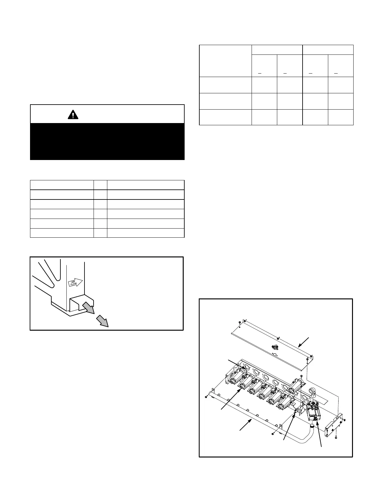
Burners
Clean the burners as follows:
1- Turn off the electrical power and the gas supply to the
unit.
2- Remove the burner compartment access panel.
3- Remove top burner box panel. See figure 8 or 9.
4- Remove two screws securing burners to burner support
and lift the burners from the orifices. See figure 8 or 9.
Clean as necessary. Spark gap on ignition electrode
must be properly set. Refer to the Heating Adjustment
section in the installation instructions.
5- Replace burners and screws securing burner.
Replace the top burner box panel and burner
compartment access panel.
6- Turn on the electrical power and the gas supply to the
unit. Follow the operating instructions attached to the
unit and use the inspection port in the access panel
to check the flame.
FIGURE 8
BURNER BOX ASSEMBLY
036-072 UNITS
GAS VALVE
GAS
MANIFOLD
FLAME
SENSOR
BURNERS
IGNITOR
TOP BURNER
BOX PANEL
 Loading...
